Chrysler Le Baron, Dodge Dynasty, Plymouth Acclaim. Manual — part 305

(5) For installation reverse above procedures. Seat
sensor assembly by hand to insure proper gear en-
gagement. Tighten retaining bolt to 7 N
Im (60 in.
lbs.) torque.
ELECTRONIC AUTOMATIC TRANSAXLE
VEHICLE SPEED SENSOR REPLACEMENT
The output vehicle speed sensor is located to the
left of the manual shift lever.
(1) Raise and support vehicle on safety stands.
(2) Remove vehicle speed sensor (Fig. 27).
(3) For installation, reverse above procedures.
VEHICLE SPEED SENSOR TEST
For testing of the vehicle speed and related compo-
nents, refer to the Powertrain Diagnostics Test Pro-
cedure Manual.
PRINTED CIRCUIT BOARD REPLACEMENT
(1) Remove cluster assembly, refer to Cluster As-
sembly Replacement.
(2) Twist out all lamp sockets.
(3) Remove screws securing printed circuit board
to cluster housing (Fig. 11).
(4) Pull printed circuit board straight out and
avoid bending the board.
(5) For installation reverse above procedures. Be
sure that all gauge pins are carefully aligned.
CLUSTER LAMPS REPLACEMENT
All cluster lamps are one-piece lamp and socket as-
semblies. Can be replaced by removing cluster as-
sembly from instrument panel. Replace appropriate
lamp shown in rear view of cluster (Fig. 28).
Fig. 24 Speedometer Pins
Fig. 25 Vehicle Speed Sensor and Connector
Fig. 26 Vehicle Speed Sensor and Speedometer
Pinion
Fig. 27 Vehicle Speed Sensor Removal
8E - 32
INSTRUMENT PANEL AND GAUGES
Ä
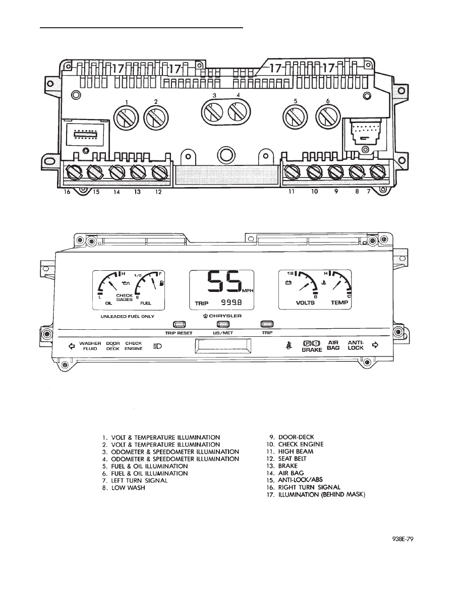
Fig. 28 Instrument Cluster Illumination Lamp
Ä
INSTRUMENT PANEL AND GAUGES
8E - 33
ELECTRONIC CLUSTER
SELF DIAGNOSTIC SYSTEM
The electronic clusters have an internal diagnostics
routing to isolate problems within the cluster or CCD
Bus.
Using the cluster Self-Diagnostic Test will deter-
mine whether the problem is within the cluster or
outside of cluster (Fig. 29 and 30).
Successful completion of the Self Diagnostic Test
indicates that the problem is in the CCD Bus, inter-
facing modules, connectors, or sensors outside of the
cluster. Refer to Fig. 31 for terminal listing.
CONDITION: CLUSTER DISPLAYS DO NOT
ILLUMINATE AFTER VEHICLE IS STARTED
PROCEDURE
(1) Check fuses and verify battery and ignition
voltage at cluster connector.
(2) Check ground from cluster connector to instru-
ment panel ground stud.
CONDITION: CLUSTER ASTERISK (*)
FLASHES, CLUSTER DISPLAYS NOT
INDICATING CORRECT DATA.
PROCEDURE
CCD bus problem. Use the Body Chassis Diagnos-
tic Manual to diagnose CCD Bus.
CONDITION: SPEEDOMETER AND ODOMETER
ARE INOPERATIVE OR OPERATES
INTERMITTENTLY
PROCEDURE
(1) If speedometer reads 0, or odometer is blank,
and cluster asterisk is flashing, use the Body Chassis
Diagnostic Manual to diagnose CCD Bus problem.
(2) If cluster asterisk is not flashing, check for de-
fective vehicle speed sensor or speed sensor wiring.
CONDITION: OIL GAUGE, FUEL GAUGE,
TEMPERATURE GAUGE, OR VOLTAGE GAUGE
INOPERATIVE
PROCEDURE
If any gauge gives no indication and cluster aster-
isk is flashing, use the Body Chassis Manual to diag-
nose CCD Bus problem.
If cluster asterisk is not flashing:
(1) Check for defective sending unit or wiring.
(a) Sending units and wiring can be checked by
grounding the connector leads, at the sending unit,
in the vehicle.
(b) With the ignition in the ON position, a
grounded input will cause the oil, fuel, or temper-
ature gauge to read maximum.
(2) If the problem is with the oil, temperature, or
fuel gauge, check the body controller. If the problem
is with the voltage gauge, check the powertrain con-
trol module operation.
CONDITION: CLUSTER DISPLAY DOES NOT
DIM WHEN HEADLAMP SWITCH IS
ACTIVATED AND RHEOSTAT ROTATED
PROCEDURE
If the cluster asterisk is flashing, Refer to the Body
Chassis Diagnostic Manual to diagnose the CCD Bus.
If the cluster asterisk is not flashing:
(1) Check fuses in headlamp circuit.
(2) Check for loose connections or defective wiring
for headlamp switch to body controller.
(3) Check for defective headlamp switch. The elec-
tronic instrument cluster receives the display inten-
sity status from the body controller via the CCD Bus.
CONDITION: SEAT BELT WARNING LAMP
DOES NOT ILLUMINATE
PROCEDURE
Turn on ignition. Lamp should illuminate for six
seconds. If not:
(1) Check for burned out lamp and retest.
(2) Replace cluster.
CONDITION: LOW WASHER, DOOR/DECK, OR
MALFUNCTION INDICATOR (CHECK ENGINE)
LAMP, DO NOT ILLUMINATE
PROCEDURE
(1) Perform cluster self-diagnostics to determine if
lamp will illuminate. If lamp does not, check for
burned out lamp, replace and retest.
(2) If cluster asterisk is flashing, Refer to the Body
Chassis Diagnostic Manual to diagnose CCD Bus.
(3) If cluster asterisk is not flashing:
(a) For low washer fluid or door/deck, check in-
puts to body controller.
(b) For malfunction indicator (check engine),
check powertrain control module operation.
CONDITION: ODOMETER DISPLAY IS BLANK.
THE ODOMETER VALUE IS NO LONGER
RETAINED IN THIS ELECTRONIC CLUSTER.
THIS TAKES PLACE IN THE BODY
CONTROLLER
PROCEDURE
(1) If cluster asterisk is flashing, Refer to the Body
Chassis Diagnostic Manual to diagnose CCD Bus.
(2) If cluster asterisk is not flashing, perform clus-
ter self-diagnostics. If code 921 appears in the odom-
eter display, replace body controller for odometer
failure.
8E - 34
INSTRUMENT PANEL AND GAUGES
Ä
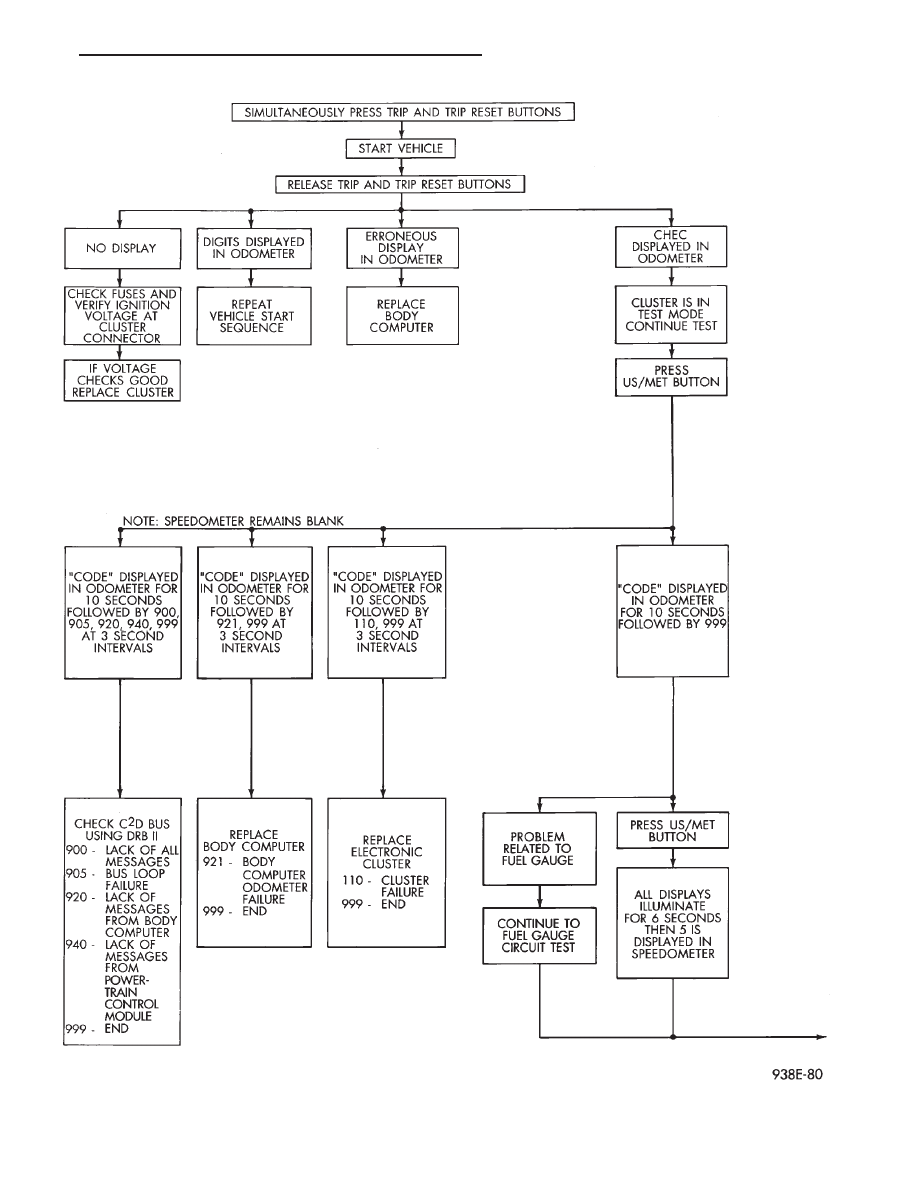
Fig. 29 Electronic Cluster Self-Diagnostic Test
Ä
INSTRUMENT PANEL AND GAUGES
8E - 35
Нет комментариевНе стесняйтесь поделиться с нами вашим ценным мнением.
Текст