Chrysler Le Baron, Dodge Dynasty, Plymouth Acclaim. Manual — part 306
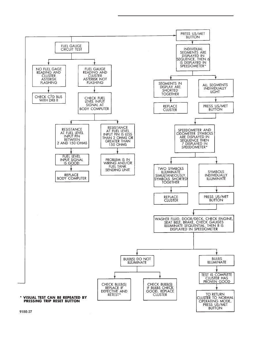
Fig. 30 Electronic Cluster Self-Diagnostic Test Continued
8E - 36
INSTRUMENT PANEL AND GAUGES
Ä
CONDITION: US/METRIC MODES WILL NOT
TOGGLE OR TRIP ODOMETER WILL NOT
RESET
PROCEDURE
(1) Perform cluster self-diagnostics to determine if
push buttons are operational.
(2) Refer to the Body Chassis Diagnostic Manual
to diagnose CCD Bus. The US/Metric toggle and trip
odometer reset are activated over the CCD Bus.
ODOMETER ADJUSTMENT
The odometer memory is no longer retained in the
cluster. This information is stored in the body con-
troller. Therefore, there is no adjustment procedure.
If the cluster is replaced odometer value will not
change. If the body controller is replaced the mileage
may be transferred using the DRB II. Refer to the
Body Chassis Diagnostic Manual for the procedure.
SWITCH AND PANEL COMPONENT SERVICE
MESSAGE CENTER REPLACEMENT
(1) Remove upper cluster bezel (Fig. 32).
(2) Remove two attaching screws (Fig. 33).
(3) Disconnect wiring connector and remove mes-
sage center.
(4) For installation reverse above procedures.
AIR CONDITIONING CONTROL
REPLACEMENT
(1) Remove upper cluster bezel (Fig. 32).
(2) Remove two control mounting screws.
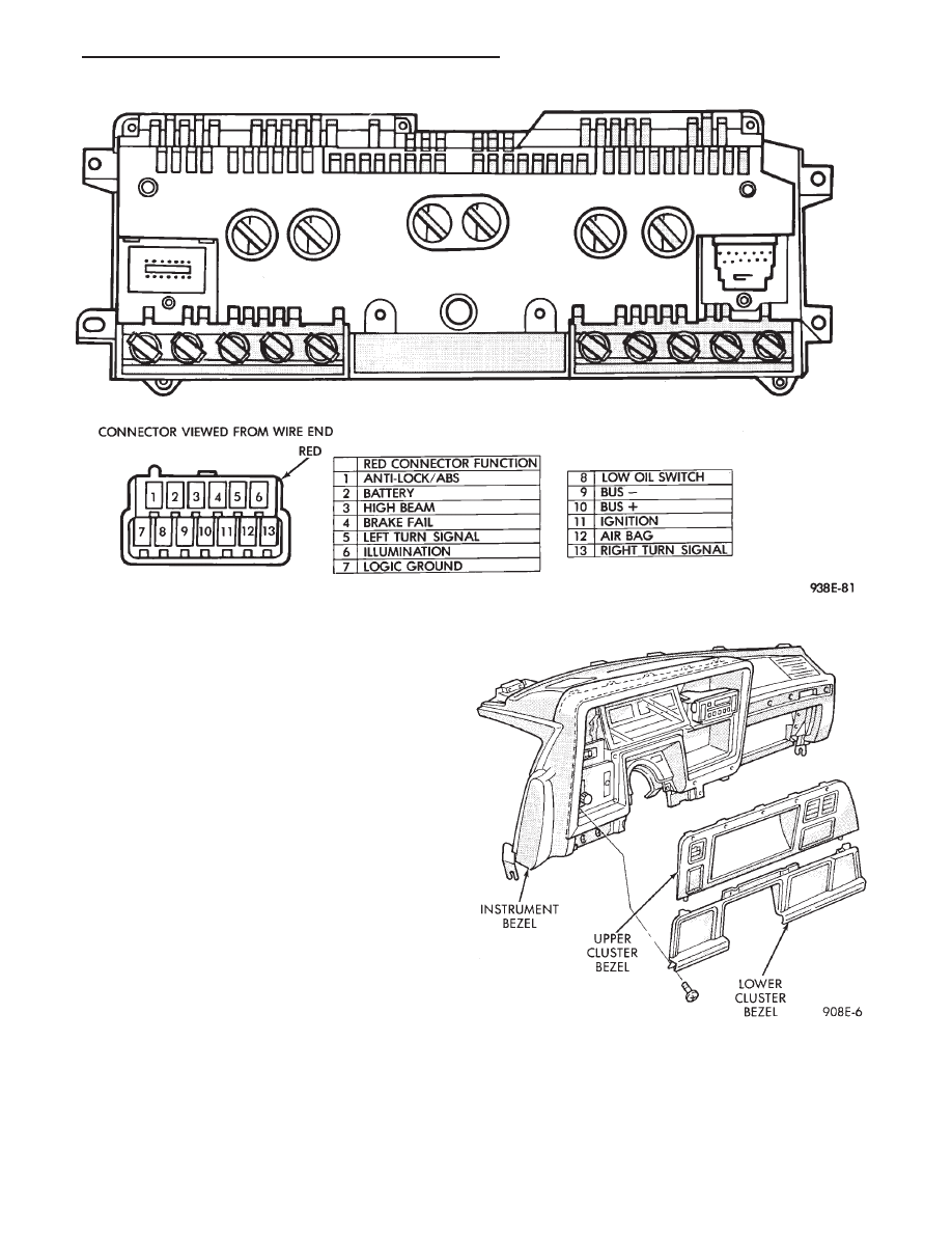
Fig. 31 Cluster Connector
Fig. 32 Cluster Bezel
Ä
INSTRUMENT PANEL AND GAUGES
8E - 37
(3) Slide control rearward, disconnect cable, vac-
uum harness and electrical wiring (Fig. 34).
(4) Remove control.
(5) For installation reverse above procedures.
AUTOMATIC TEMPERATURE CONTROL LAMP
REPLACEMENT
(1) Remove automatic temperature control from in-
strument panel.
(2) Remove top cover screw and unsnap cover from
control (Fig. 35).
(3) Remove four screws that connect computer
housing to the button housing.
(4) Unsnap the button housing from the computer
housing.
(5) Remove lamps by turning in a counter clock-
wise direction and install lamps by turning in a
clockwise direction.
(6) For
installation
reverse
above
procedures.
When finish perform ATC system function test.
HEADLAMP AND ACCESSORY SWITCH
MODULE REPLACEMENT
(1) Remove cluster bezel (Fig. 32).
(2) Remove four screws attaching module to instru-
ment panel (Fig. 36).
(3) Disconnect all wiring connectors to remove
module.
(4) For installation reverse above procedures.
HEADLAMP SWITCH REPLACEMENT
(1) Remove headlamp and accessory switch module
from instrument panel (Fig. 36).
(2) Press button on underside of headlamp switch
and pull knob and shaft to remove.
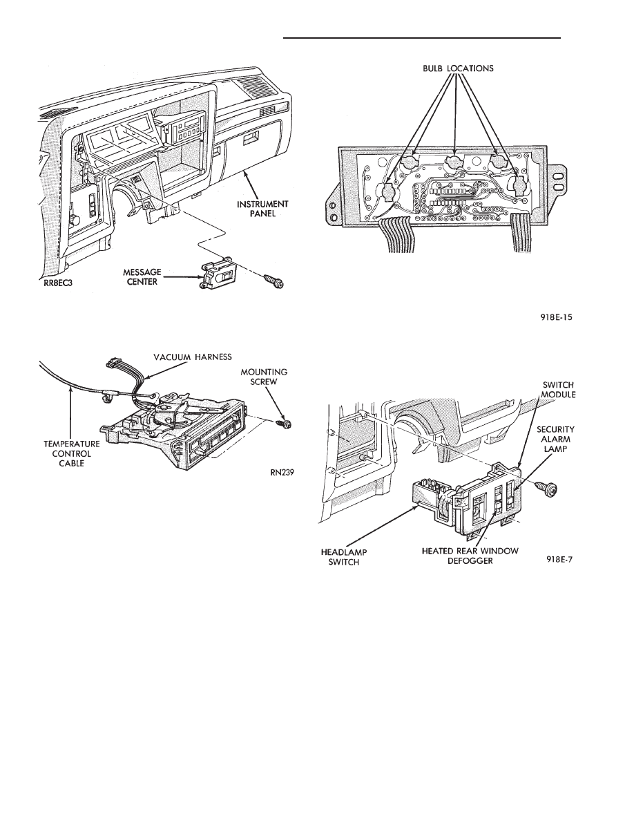
Fig. 33 Message Center
Fig. 34 A/C Control
Fig. 35 Automatic Temperature Control Lamp
Fig. 36 Headlamp and Accessory Switch Module
8E - 38
INSTRUMENT PANEL AND GAUGES
Ä
(3) Remove switch assembly and escutcheon from
switch module by removing four attaching screws
(Fig. 37).
(4) Remove headlamp switch mounting plate from
switch by removing retaining nut.
(5) For installation reverse above procedures.
REAR WINDOW DEFOGGER SWITCH
REPLACEMENT
(1) Remove headlamp and accessory switch module
from instrument panel (Fig. 36).
(2) Remove rear window defogger switch by de-
pressing snap-in clips on top and bottom of switch.
(3) For installation reverse above procedures.
HOOD RELEASE HANDLE AND CABLE
REPLACEMENT
(1) Disconnect hood release cable at hood latch.
(2) Remove two screws from underside of hood re-
lease handle.
(3) Pull mechanism assembly rearward to remove.
(4) For installation reverse above procedures.
PARK BRAKE RELEASE HANDLE AND LINK
REPLACEMENT
(1) Remove left side under panel silencer.
(2) Remove park brake link from lever on park
brake mechanism.
(3) Remove upper and lower cluster bezels.
(4) Pull park brake release handle and remove
screw.
(5) Remove column cover/park brake release han-
dle assembly by removing four remaining screws.
(6) For installation reverse above procedures.
LAMP OUTAGE MODULE REPLACEMENT
(1) Disconnect battery negative cable and isolate
or remove fuse #13 prior to removing switch or wires
may short to ground.
(2) Remove lower right instrument panel silencer.
(3) Remove glove box and ash receiver module.
(4) Remove three screws attaching the mounting
bracket to instrument panel.
(5) Lower bracket and module assembly, to discon-
nect wire connectors.
(6) Remove two screws attaching the Lamp Outage
Module to bracket.
(7) Remove two screws attaching the security mod-
ule to bracket.
(8) To installation reverse above procedures.
BODY CONTROLLER REPLACEMENT
(1) Remove right side door sill and kick panel trim
five screws (Fig. 38).
(2) Disconnect body controller wiring.
(3) Remove controller retaining nuts.
(4) For installation reverse above procedures.
GLOVE BOX/ASH RECEIVER ASSEMBLY
REPLACEMENT
(1) Disconnect battery negative cable and isolate
or remove fuse #13 prior to removing switch or wires
may short to ground.
(2) Remove center support cover/floor console as
necessary.
(3) Disconnect glovebox/Ash receiver wiring con-
nectors (Fig. 39).
(4) Remove ten screws around edge of glovebox/ash
receiver assembly.
(5) Remove glovebox/ash receiver module from in-
strument panel.
(6) For installation reverse above procedures.
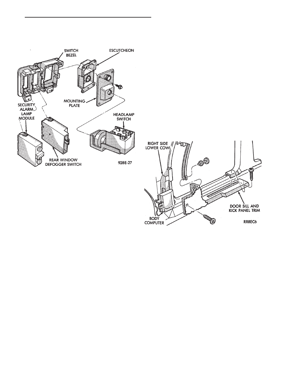
Fig. 37 Headlamp and Accessory Switch
Fig. 38 Body Controller Location
Ä
INSTRUMENT PANEL AND GAUGES
8E - 39
Нет комментариевНе стесняйтесь поделиться с нами вашим ценным мнением.
Текст