Chrysler Le Baron, Dodge Dynasty, Plymouth Acclaim. Manual — part 56

(3) Loosen fuel return hose clamp and remove fuel
return hose from nipple.
(4) Remove vacuum hose from fuel pressure regu-
lator. (Fig. 13).
(5) Remove screw holding fuel return tube to the
intake manifold.
(6) Remove fuel pressure regulator screws. Remove
fuel pressure regulator from engine.
INSTALLATION
(1) Lubricate O-ring on fuel pressure regulator
with clean 30 weight engine oil.
(2) Install fuel pressure regulator into fuel rail.
Tighten screws to 10 N
Im (90 in. lbs.) torque.
(3) Install screw holding fuel return tube clamp in
place. Tighten screw to 10 N
Im (95 in. lbs.) torque.
(4) Connect vacuum hose to fuel pressure regula-
tor.
(5) Connect fuel return hose to fuel return tube.
Tighten hose clamp to 1 N
Im (10 in. lbs.) torque.
(6) Connect negative battery cable.
CAUTION: When using the ASD Fuel System Test,
the Auto Shutdown (ASD) Relay remains energized
for either 7 minutes, until the test is stopped, or un-
til the ignition switch is turned to the Off position.
(7) With the ignition key in ON position, access
the DRBII scan tool’s ASD Fuel System Test to pres-
surize the fuel system. Check for leaks.
FUEL INJECTORS
WARNING: THE 3.0L MPI FUEL SYSTEM IS UNDER
A CONSTANT PRESSURE OF APPROXIMATELY 330
KPA (48 PSI). PERFORM FUEL PRESSURE RE-
LEASE
PROCEDURE
BEFORE
SERVICING
THE
FUEL INJECTORS.
REMOVAL
(1) Perform the Fuel Pressure Release Procedure.
(2) Disconnect negative cable from battery.
The fuel rail must be removed first to service the
injectors. Refer to Fuel Injector Rail Assembly Re-
moval in this section.
(3) Label each injector connector with its cylinder
number. Disconnect electrical connector from injec-
tor.
(4) Position fuel rail assembly so that the fuel in-
jectors are easily accessible.
(5) Remove injector clip from fuel rail and injector
(Fig. 14).
(6) Pull injector straight out of fuel rail receiver
cup (Fig. 15).
Fig. 13 Fuel Pressure Regulator
Fig. 14 Fuel Injector and Rail
Fig. 15 Servicing Fuel Injector
14 - 142
FUEL SYSTEMS
Ä
(7) Check injector O-ring for damage. If O-ring is
damaged, it must be replaced. If injector is to be re-
used, a protective cap must be installed on the injec-
tor tip to prevent damage.
(8) Repeat procedure for remaining injectors.
INSTALLATION
(1) Before installing an injector, the rubber O-ring
must be lubricated with a drop of clean engine oil to
aid in installation.
(2) Being careful not to damage O-ring, install in-
jector nozzle end into fuel rail receiver cap (Fig. 15).
(3) Install injector clip by sliding open end into top
slot of the injector. The edge of the receiver cup will
slide into the side slots of clip (Fig. 14).
(4) Repeat steps for remaining injectors.
(5) Install fuel rail assembly. Refer to Fuel Rail
Assembly Installation in this section.
(6) Connect electrical connectors to injectors in cor-
rect order.
(7) Connect negative battery cable.
CAUTION: When using the ASD Fuel System Test,
the Auto Shutdown (ASD) Relay remains energized
for either 7 minutes, until the test is stopped, or un-
til the ignition switch is turned to the Off position.
(8) With the ignition key in ON position, access
the DRBII scan tool ASD Fuel System Test to pres-
surize the fuel system. Check for leaks.
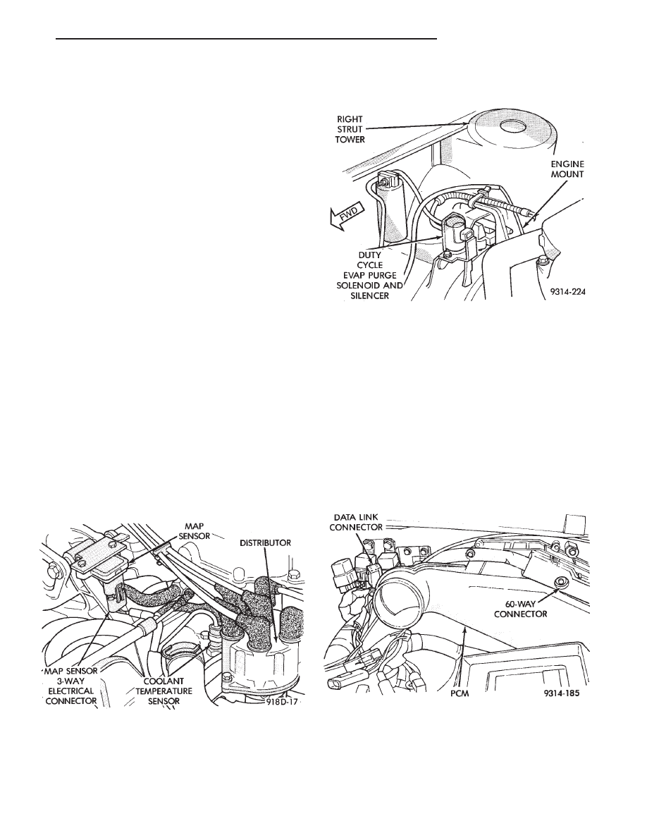
MANIFOLD ABSOLUTE PRESSURE (MAP) SENSOR
(1) Remove vacuum hose and mounting screws
from manifold absolute pressure (MAP) sensor (Fig.
16).
(2) Disconnect electrical connector from sensor. Re-
move sensor.
(3) Reverse the above procedure for installation.
CANISTER PURGE SOLENOID SERVICE
(1) Remove vacuum hose and electrical connector
from solenoid (Fig. 17).
(2) Slide solenoid and silencer assembly off of
bracket.
(3) Reverse above procedure to install.
PCM
(1) Remove air cleaner duct from PCM.
(2) Disconnect negative cable from battery. Discon-
nect positive cable from battery.
(3) Remove battery holddown. Remove battery.
(4) Remove PCM mounting screws (Fig. 18, Fig. 19
or Fig. 20).
(5) Remove the electrical connector from PCM. Re-
move PCM.
(6) Reverse the above procedure for installation.
Fig. 16 Manifold Absolute Pressure Sensor
Fig. 17 Canister Purge Solenoid
Fig. 18 PCM—AA Body
Ä
FUEL SYSTEMS
14 - 143
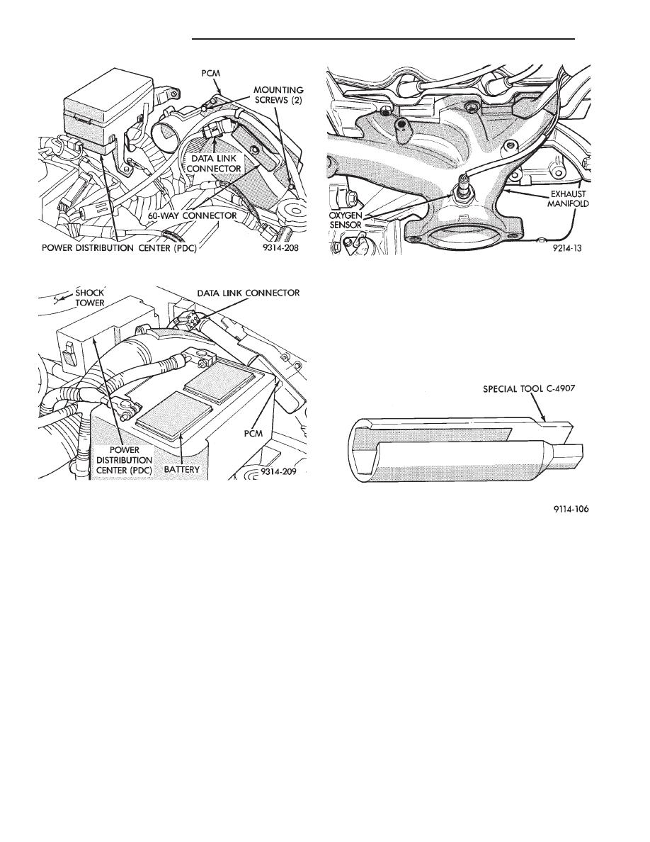
HEATED OXYGEN SENSOR (O
2
SENSOR)
The oxygen sensor is installed in the exhaust man-
ifold (Fig. 21).
CAUTION: Do not pull on the oxygen sensor wires
when disconnecting the electrical connector.
WARNING: THE EXHAUST MANIFOLD MAY BE EX-
TREMELY HOT. USE CARE WHEN SERVICING THE
OXYGEN SENSOR.
(1) Disconnect oxygen sensor electrical connector.
(2) Remove sensor using Tool C-4907 (Fig. 22).
Slightly tightening the sensor can ease removal.
When the sensor is removed, the exhaust manifold
threads must be cleaned with an 18 mm X 1.5 + 6E tap.
If using original sensor, coat the threads with Loctite
771-64 anti-seize compound or equivalent. New sen-
sors are packaged with compound on the threads and
do not require additional compound. The sensor must
be tightened to 27 N
Im (20 ft. lbs.) torque.
Fig. 19 PCM—AC Body
Fig. 20 PCM—AG and AJ Bodies
Fig. 21 Heated Oxygen Sensor
Fig. 22 Oxygen Sensor Socket
14 - 144
FUEL SYSTEMS
Ä
3.3L AND 3.8L MULTI-PORT FUEL INJECTION—SYSTEM OPERATION
INDEX
page
page
Air Conditioning (A/C) Clutch Relay—PCM Output
. 150
Air Conditioning Switch Sense—PCM Input
. . . . 147
Auto Shutdown (ASD) Relay and Fuel Pump
Relay—PCM Output
. . . . . . . . . . . . . . . . . . . . 151
Battery Voltage—PCM Input
. . . . . . . . . . . . . . . 147
Brake Switch—PCM Input
. . . . . . . . . . . . . . . . . 147
Camshaft Position Sensor—PCM Input
. . . . . . . 147
Canister Purge Solenoid—PCM Output
. . . . . . . 151
CCD Bus
. . . . . . . . . . . . . . . . . . . . . . . . . . . . . . 146
Crankshaft Position Sensor—PCM Input
. . . . . . 148
Data Link Connector—PCM Output
. . . . . . . . . . 152
Electric EGR Transducer (EET) Solenoid—PCM
Output
. . . . . . . . . . . . . . . . . . . . . . . . . . . . . . 152
Engine Coolant Temperature Sensor—PCM Input
. 148
Fuel Injectors and Fuel Rail Assembly
. . . . . . . . 155
Fuel Injectors—PCM Output
. . . . . . . . . . . . . . . 152
Fuel Pressure Regulator
. . . . . . . . . . . . . . . . . . 156
Fuel Supply Circuit
. . . . . . . . . . . . . . . . . . . . . . 155
General Information
. . . . . . . . . . . . . . . . . . . . . . 145
Generator Field—PCM Output
. . . . . . . . . . . . . . 150
Heated Oxygen Sensor (O
Sensor)—PCM Input
. 149
Idle Air Control Motor—PCM Output
. . . . . . . . . 151
Ignition Coil—PCM Output
. . . . . . . . . . . . . . . . . 153
Malfunction Indicator Lamp (Check Engine
Lamp)—PCM Output
. . . . . . . . . . . . . . . . . . . 151
Manifold Absolute Pressure (MAP) Sensor—PCM
Input
. . . . . . . . . . . . . . . . . . . . . . . . . . . . . . . . 149
Modes of Operation
. . . . . . . . . . . . . . . . . . . . . . 153
Powertrain Control Module
. . . . . . . . . . . . . . . . . 146
Radiator Fan Relay—PCM Output
. . . . . . . . . . . 153
Speed Control Solenoids—PCM Output
. . . . . . . 153
Speed Control—PCM Input
. . . . . . . . . . . . . . . . 150
System Diagnosis
. . . . . . . . . . . . . . . . . . . . . . . 146
Tachometer—PCM Output
. . . . . . . . . . . . . . . . . 153
Throttle Body
. . . . . . . . . . . . . . . . . . . . . . . . . . . 155
Throttle Position Sensor (TPS)—PCM Input
. . . . 150
Transaxle Control Module—PCM Output
. . . . . . 152
Transaxle Park/Neutral Switch—PCM Input
. . . . 150
Vehicle Speed and Distance Input—PCM Input
. 150
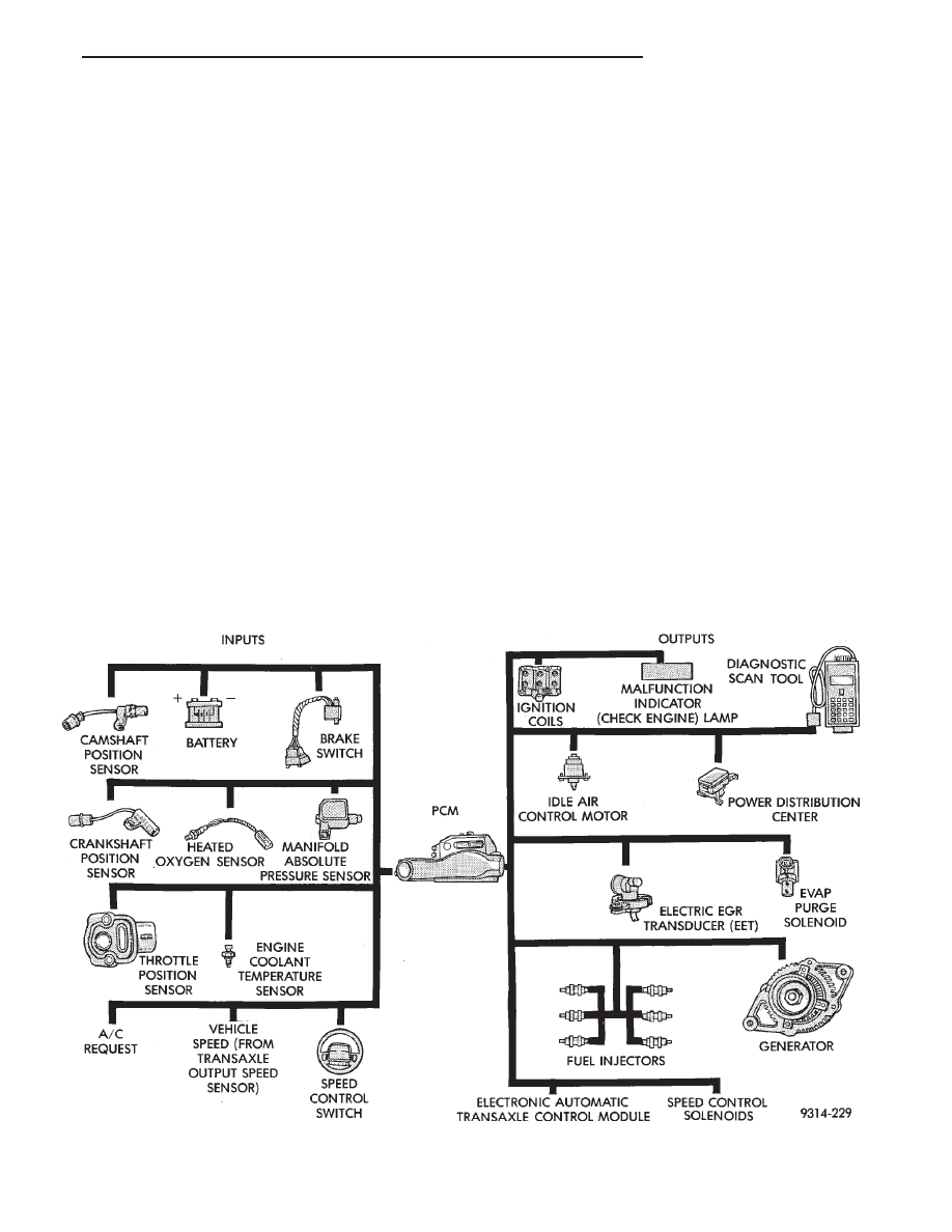
GENERAL INFORMATION
3.3L and 3.8L engines use a sequential Multi-port
Electronic Fuel Injection system (Fig. 1). The MPI
system is computer regulated and provides precise
air/fuel ratios for all driving conditions.
The MPI system is operated by the powertrain con-
trol module (PCM).
Fig. 1 Multi-Port Fuel Injection Components
Ä
FUEL SYSTEMS
14 - 145
Нет комментариевНе стесняйтесь поделиться с нами вашим ценным мнением.
Текст