Chrysler Le Baron, Dodge Dynasty, Plymouth Acclaim. Manual — part 55
3.0L MULTI-PORT FUEL INJECTION—SERVICE PROCEDURES
INDEX
page
page
Idle Air Control Motor
. . . . . . . . . . . . . . . . . . . . 138
Canister Purge Solenoid Service
. . . . . . . . . . . . 143
Fuel Injector Rail Assembly
. . . . . . . . . . . . . . . . 139
Fuel Injectors
. . . . . . . . . . . . . . . . . . . . . . . . . . 142
Fuel Pressure Regulator Service
. . . . . . . . . . . . 141
Fuel System Pressure Release Procedure
. . . . . 138
Heated Oxygen Sensor (O
2
Sensor)
. . . . . . . . . 144
Manifold Absolute Pressure (MAP) Sensor
. . . . . 143
PCM
. . . . . . . . . . . . . . . . . . . . . . . . . . . . . . . . . 143
Throttle Body
. . . . . . . . . . . . . . . . . . . . . . . . . . . 138
Throttle Body Service
. . . . . . . . . . . . . . . . . . . . 138
Throttle Position Sensor
. . . . . . . . . . . . . . . . . . 138
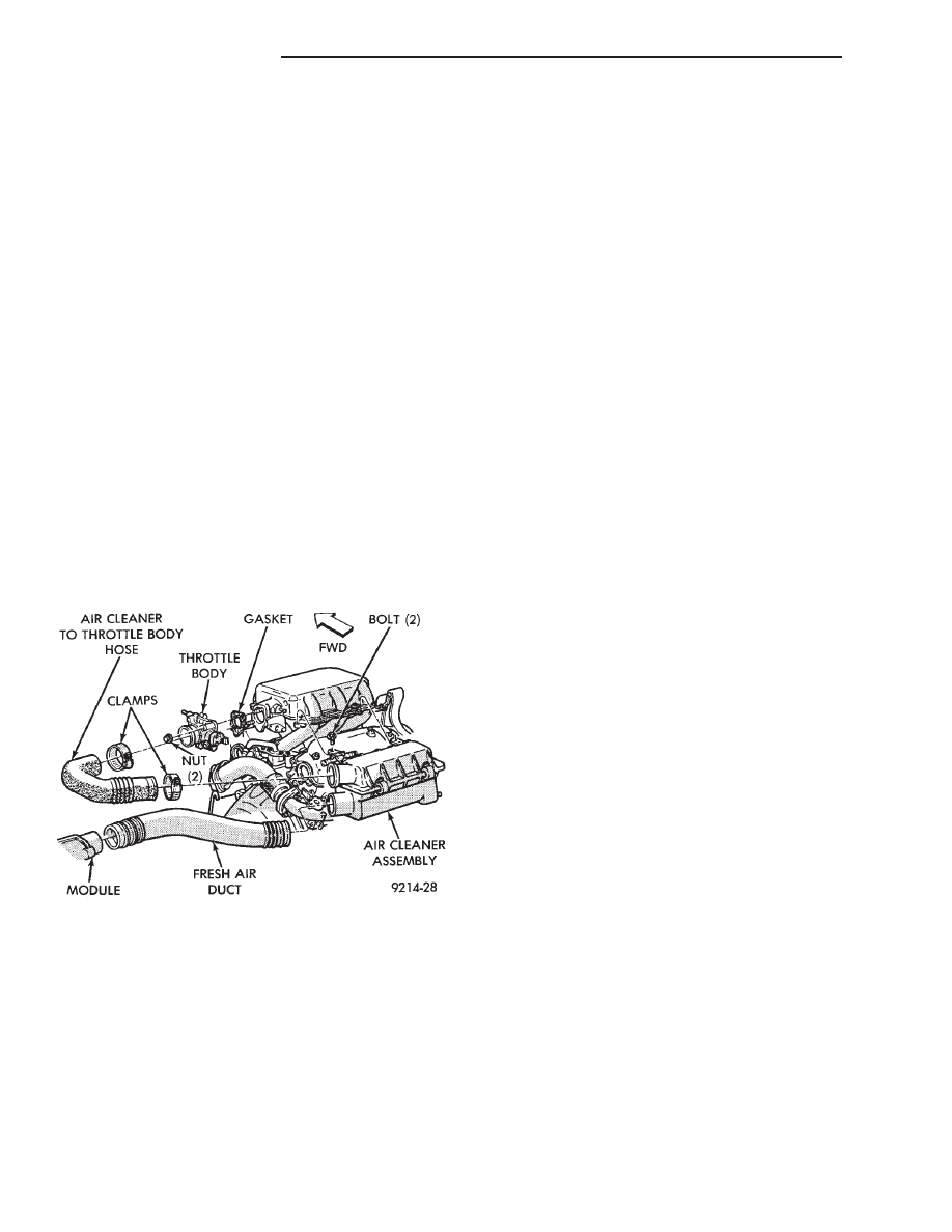
THROTTLE BODY SERVICE
(1) Disconnect negative battery cable.
(2) Remove air cleaner hose clamp to throttle body
and remove hose. (Fig. 1)
(3) Remove throttle cable and transaxle linkage.
(4) Disconnect idle air control motor and throttle
position sensor (TPS) wiring connectors.
(5) Disconnect vacuum hoses from throttle body.
(6) Remove throttle body to intake manifold attach-
ing nuts. Remove engine harness wiring bracket.
(7) Remove throttle body and gasket.
(8) Reverse the above procedures for installation.
Tighten throttle body mounting nuts to 25 N
Im (225
in. lbs.) torque.
THROTTLE BODY
When servicing body components, always assemble
components with new O-rings and seals where appli-
cable (Fig. 2). Never use lubricants on O-rings or seals,
damage may result. If assembly of component is diffi-
cult, use water to aid assembly. Use care when remov-
ing hoses to prevent damage to hose or hose nipple.
FUEL SYSTEM PRESSURE RELEASE PROCEDURE
The 3.0L MPI fuel system is under a constant
pressure of approximately 330 kPa (48 psi). Be-
fore servicing the fuel pump, fuel lines, fuel fil-
ter, throttle body or fuel injectors, the fuel sys-
tem pressure must be released.
(1) Loosen fuel filler cap to release fuel tank pres-
sure.
(2) Disconnect injector wiring harness from engine
harness. Refer to Group 8W, Wiring Diagrams.
(3) Connect one end of a jumper wire to the A142
circuit terminal of the fuel rail harness connector.
(4) Connect the other end of the jumper wire to a 12
volt power source.
(5) Connect one end of a jumper wire to a good
ground source.
(6) Momentarily ground one of the injectors by con-
necting the other end of the jumper wire to an injector
terminal in the harness connector. Repeat procedure
for 2 to 3 injectors.
(7) Continue fuel system service.
THROTTLE POSITION SENSOR
REMOVAL
(1) Disconnect negative cable from battery.
(2) Remove electrical connector from throttle posi-
tion sensor.
(3) Remove throttle position sensor mounting screws
(Fig. 3).
(4) Lift throttle position sensor off throttle shaft.
INSTALLATION
(1) Install throttle position sensor on throttle shaft.
Install mounting screws. Tighten screw to 2 N
Im (17
in. lbs.) torque.
(2) Connect electrical connector to throttle position
sensor.
(3) Connect negative cable to battery.
IDLE AIR CONTROL MOTOR
REMOVAL
(1) Disconnect negative cable from battery.
(2) Remove electrical connector from idle air control
motor.
(3) Remove idle air control motor mounting screws
(Fig. 4).
Fig. 1 Throttle Body
14 - 138
FUEL SYSTEMS
Ä

(4) Remove idle air control motor from throttle
body. Ensure the O-ring is removed with the motor.
INSTALLATION
(1) New idle air control motors have a new O-ring
installed on it. If pintle measures more than 1 inch
(25 mm) it must be retracted. Use the DRBII scan
tool Idle Air Control Motor Open/Close Test to re-
tract the pintle.
(2) Carefully place idle air control motor into
throttle body.
(3) Install mounting screws. Tighten screws to 2
N
Im (17 in. lbs.) torque.
(4) Connect electrical connector to motor.
(5) Connect negative cable to battery.
FUEL INJECTOR RAIL ASSEMBLY
REMOVAL
WARNING: THE 3.0L MPI FUEL SYSTEM IS UNDER
A CONSTANT PRESSURE OF APPROXIMATELY 330
KPA (48 PSI). PERFORM FUEL PRESSURE RE-
LEASE
PROCEDURE
BEFORE
SERVICING
THE
FUEL RAIL OR FUEL INJECTORS.
(1) Perform the Fuel Pressure Release Procedure.
(2) Disconnect negative cable from battery.
(3) Remove air cleaner to throttle body hose.
(4) Remove throttle cable (Fig. 5).
(5) Disconnect electrical connectors from the idle
air control motor and throttle position sensor (TPS).
Fig. 2 Throttle Body 3.0L
Fig. 3 Servicing Throttle Position Sensor
Fig. 4 Servicing Idle Air Control Motor
Ä
FUEL SYSTEMS
14 - 139

(6) Remove vacuum hose harness from throttle
body (Fig. 6).
(7) Remove vacuum hoses from air intake plenum
(Fig. 6).
(8) If equipped with EGR, remove the EGR tube
flange from intake plenum (Fig. 7).
(9) Remove the wiring connector from the coolant
temperature sensor (Fig. 8).
(10) Remove vacuum connections from air intake
plenum vacuum connector (Fig. 8).
(11) Remove fuel hoses from fuel rail (Fig. 8).
(12) Remove air intake plenum to intake manifold
mounting fasteners (Fig. 9).
(13) Remove ignition coil.
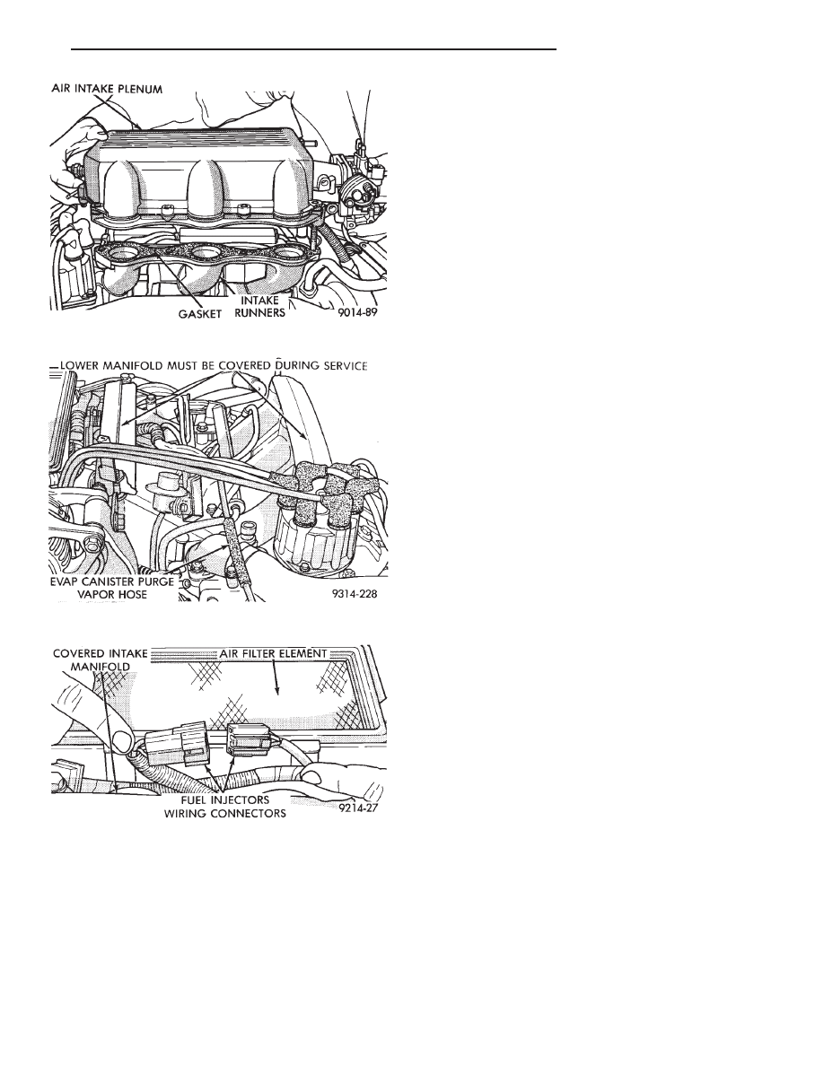
(14) Remove air intake plenum (Fig. 10).
(15) Cover intake manifold while servicing injector
fuel rail (Fig. 11).
(16) Remove vacuum hoses from fuel rail (Fig. 11).
(17) Disconnect fuel injector wiring harness from
engine wiring harness (Fig. 12).
CAUTION: Do not damage the injector O-Rings
when removing the injectors and fuel rail assem-
bly.
Fig. 5 Throttle Cable Attachment
Fig. 6 Electrical and Vacuum Connection to Throttle
Body
Fig. 7 EGR Tube to Intake Plenum
Fig. 8 Coolant Temperature Sensor
Fig. 9 Air Intake Plenum to Intake Manifold
Attaching Fasteners
14 - 140
FUEL SYSTEMS
Ä
(18) Remove fuel rail mounting bolts. Lift fuel rail
assembly off of intake manifold.
INSTALLATION
(1) Be sure injectors are seated into the receiver
cup with lock ring in place.
(2) Make sure the injector holes are clean and all
plugs have been removed.
(3) To ease installation, lubricate injector O-ring
with a drop of clean engine oil.
(4) Put the tip of each injector into their ports.
Push the assembly into place until the injectors are
seated in the ports.
(5) Install fuel rail attaching bolts. Tighten bolts
to 13 N
Im (115 in. lbs.) torque.
(6) Install fuel supply and return tube holddown
bolt and the vacuum crossover tube holddown bolt.
Tighten bolts to 10 N
Im (95 in. lbs.) torque.
(7) Connect fuel injector wiring harness to engine
wiring harness.
(8) Connect vacuum harness to fuel rail assembly.
(9) Remove covering from lower intake manifold
and clean surface.
(10) Place intake manifold gaskets with beaded
sealer up on lower manifold. Put air intake in place.
Install ignition coil. Install attaching fasteners and
tighten to 13 N
Im (115 in. lbs.) torque.
(11) Connect fuel lines to fuel rail. Tighten hose
clamps to 1 N
Im (10 in. lbs.) torque.
(12) Connect vacuum harness to air intake plenum
and fuel pressure regulator.
(13) Connect coolant temperature sensor electrical
connector to sensor.
(14) Connect EGR tube flange to intake plenum.
Tighten mounting nuts to 22 N
Im (200 in. lbs.)
torque.
(15) Connect PCV and brake booster supply hose
to intake plenum.
(16) Connect idle air control motor and throttle po-
sition sensor (TPS) electrical connectors.
(17) Connect vacuum vapor harness to throttle
body.
(18) Install throttle cable.
(19) Install air inlet hose assembly.
(20) Connect negative cable to battery.
CAUTION: When using the ASD Fuel System Test,
the Auto Shutdown (ASD) Relay remains energized
for either 7 minutes, until the test is stopped, or un-
til the ignition switch is turned to the Off position.
(21) With the ignition key in ON position, access
the DRBII scan tool ASD Fuel System Test to pres-
surize the fuel system. Check for leaks.
FUEL PRESSURE REGULATOR SERVICE
REMOVAL
WARNING: THE 3.0L MPI FUEL SYSTEM IS UNDER
A CONSTANT PRESSURE OF APPROXIMATELY 330
KPA (48 PSI). PERFORM FUEL PRESSURE RE-
LEASE
PROCEDURE
BEFORE
SERVICING
THE
FUEL PRESSURE REGULATOR.
(1) Perform the Fuel Pressure Release Procedure.
(2) Disconnect negative cable from battery.
Fig. 10 Removing Air Intake Plenum
Fig. 11 Vacuum Connections at the Fuel Rail
Fig. 12 Fuel Injector Wiring Harness
Ä
FUEL SYSTEMS
14 - 141
Нет комментариевНе стесняйтесь поделиться с нами вашим ценным мнением.
Текст