Chrysler Le Baron, Dodge Dynasty, Plymouth Acclaim. Manual — part 88
REAR SUSPENSION
INDEX
page
page
Coil Springs and Jounce Bumper
. . . . . . . . . . . . 51
General Information
. . . . . . . . . . . . . . . . . . . . . . . 50
Pivot Bushing AC AG AJ AP Body
. . . . . . . . . . . 55
Pivot Bushing AC and AY Body
. . . . . . . . . . . . . 52
Rear Axle Assembly
. . . . . . . . . . . . . . . . . . . . . . 57
Shock Absorbers
. . . . . . . . . . . . . . . . . . . . . . . . . 51
Track Bar-Brace-Bracket
. . . . . . . . . . . . . . . . . . . 52
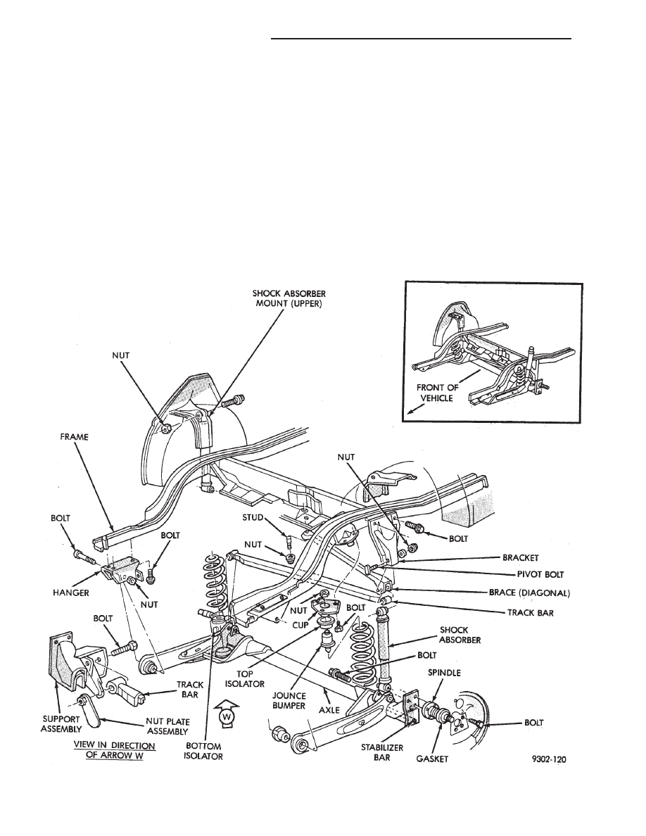
GENERAL INFORMATION
All front wheel drive passenger cars. Utilize a
Trailing Arm Twist Beam type rear axle in conjunc-
tion with coil (or air) springs (Fig. 1). The blade type
Trailing Arms, attached to body mounted pivots, pro-
vide fore and aft location of the suspension while a
Track Bar provides lateral location.
Located in line with the spindles. An open channel
section beam axle assures that the rear tires remain
parallel to each other, and essentially perpendicular
Fig. 1 Trailing Arm Rear Suspension
2 - 50
SUSPENSION AND DRIVESHAFTS
Ä
to the road surface. While being able to twist as one
wheel moves vertically with respect to the other.
Roll resistance is provided partly by the axle’s re-
sistance to twist. But primarily by a torque tube or
rod (depending on the suspension option called for)
running through the channel and attached rigidly to
its end plates by welding. Because the torque tube/
rod is an integral part of the axle assembly, it cannot
be individually replaced.
The spindles are bolted to the axle end (spindle
mounting) plates and can be individually replaced if
required. Rear wheel alignment changes require the
use of shims between the spindle and axle end plates.
SHOCK ABSORBERS
REMOVAL
(1) Raise vehicle, see Hoisting, Group 0.
(2) Support axle and remove wheel and tire assem-
bly.
(3) If equipped with air shocks, disconnect air
lines.
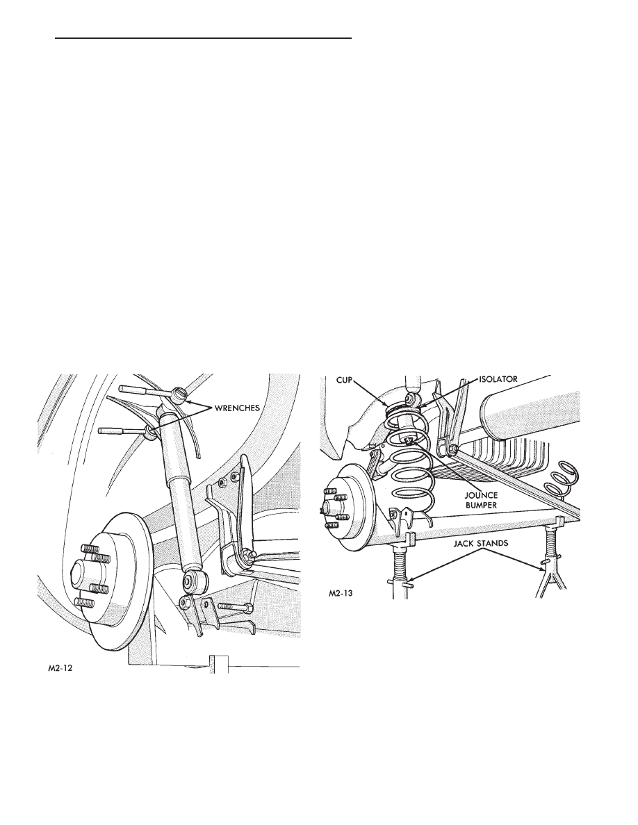
(4) Remove upper and lower shock absorber fasten-
ers, remove shock absorbers (Fig. 2).
INSPECTION
Inspect for evidence of fluid leakage from upper
end of reservoir. (Actual leakage will be a stream of
fluid running down and leaking off lower end). Slight
seepage is not unusual and will not effect perfor-
mance.
INSTALLATION
(1) Position shock absorber on car. Install upper
and lower fasteners loosely to hold shock absorber in
place.
(2) Tighten upper fastener to 61 N
Im (45 ft. lbs.)
torque. Connect air line, if so equipped.
(3) Install wheel and tire assembly, tighten wheel
stud nuts to 129 N
Im (95 ft. lbs.) torque. Lower vehi-
cle to ground.
(4) With suspension supporting the weight of the
vehicle. Tighten lower shock absorber fastener to 54
N
Im (40 ft. lbs.) torque.
COIL SPRINGS AND JOUNCE BUMPER
REMOVAL
(1) Lift vehicle see hoisting Group 0.
(2) Support axle assembly and remove both lower
shock absorber attaching bolts.
(3) Lower axle assembly until spring and spring
upper isolator can be removed (Fig. 3). Do not
stretch brake hose.
(4) Remove two screws holding cup to rail (Fig. 1).
Remove assembly.
INSTALLATION
(1) Position cup to rail. Install and tighten attach-
ing bolts to 8 N
Im (70 in. lbs.) torque.
(2) Install isolator over jounce bumper and install
spring.
(3) Raise axle and loosely assemble both shock ab-
sorber to axle mounting bolts. Remove axle support
and lower vehicle.
(4) With suspension supporting the weight of the
vehicle. Tighten both shock absorber attaching bolts
to 61 N
Im (45 ft. lbs.) torque.
Fig. 2 Remove/Install Shock Absorber Fasteners
Fig. 3 Coil Spring & Jounce Bumper
Ä
SUSPENSION AND DRIVESHAFTS
2 - 51
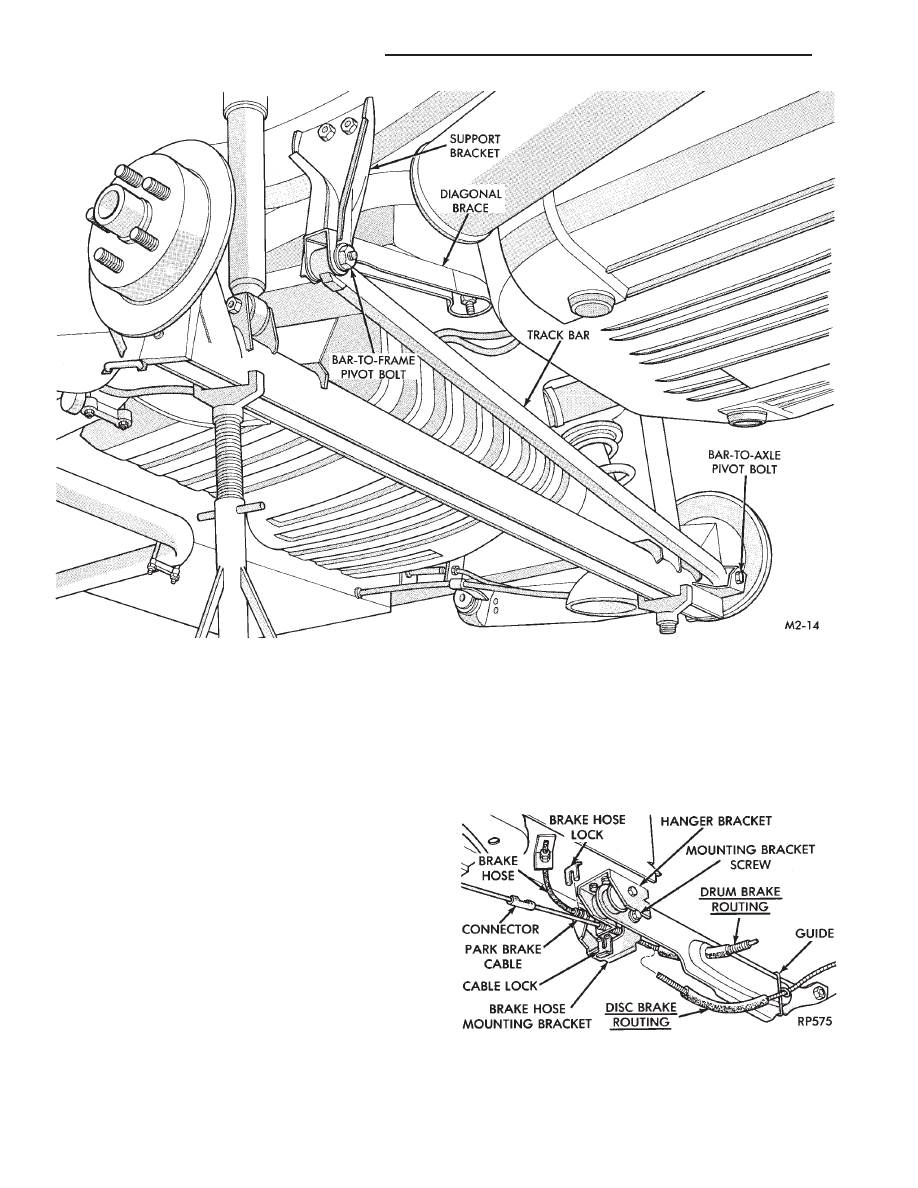
TRACK BAR-BRACE-BRACKET (FIG. 4)
REMOVAL
(1) Raise vehicle, see Hoisting, Group 0.
(2) Raise rear axle to curb height, with jack stands
(Fig. 5).
(3) Remove track bar-to-axle pivot bolt. And re-
move track bar-to-frame pivot bolt. Remove track
bar.
(4) Remove diagonal brace-to-underbody stud nut.
Remove diagonal brace.
(5) Remove two track bar bracket-to-frame rail
bolts. Remove bracket.
INSTALLATION
(1) Position support bracket on frame rail, install
and tighten (2) bolts to 54 N
Im (40 ft. lbs.) torque.
(2) Fit diagonal brace into support bracket and
over underbody stud, tighten stud nut to 75 N
Im (55
ft. lbs.) torque.
(3) Fit track bar to diagonal brace, loose assemble
pivot bolt with nut and washer on rear side. Attach
the other end of track bar to bracket on axle and
tighten to 95 N
Im (70 ft. lbs.) torque. Tighten nut on
track bar-to-frame bolt to 75 N
Im (55 ft. lbs.) torque.
PIVOT BUSHING AC AND AY BODY
REMOVE FROM VEHICLE
(1) Raise vehicle (see Hoisting, Group 0). Remove
brake hose mounting bracket screw (Fig. 5).
(2) Detach park brake cable at connector and from
hanger bracket (Fig. 5).
Fig. 4 Track Bar Brace Bracket
Fig. 5 Remove Brake Hose Mounting Bracket Screw
and Park Brake Cable
2 - 52
SUSPENSION AND DRIVESHAFTS
Ä
WARNING: WHEN REMOVING THE REAR AXLE
PIVOT BUSHING ON VEHICLES EQUIPPED WITH EI-
THER REAR COIL SPRINGS OR AIR SUSPENSION.
THE REAR AXLE MUST BE SUPPORTED BY THE
AXLE AND TRAILING ARM TO ENSURE ADEQUATE
SUPPORT OF REAR AXLE.
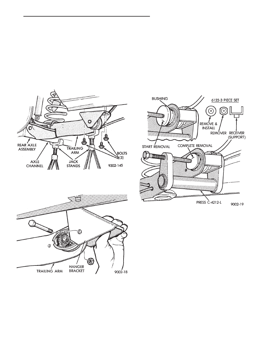
(3) Support the rear axle assembly at both the axle
channel and the trailing arm (Fig. 6). Then remove
lower shock absorber to rear axle mounting bolt (Fig.
6).
(4) Remove hanger bracket to frame rail bolts (Fig.
7).
(5) Lower axle assembly down enough to remove
pivot bolt and hanger bracket (Fig. 7). Right side
trailing arm shown.
PIVOT BUSHING REMOVAL FROM AXLE AS-
SEMBLY
Remove bushing with Remover/Installer Spe-
cial Tool C-4212-L (Press) and 3 piece set, Spe-
cial Tool 6122 (Receiver Support Bridge, Bushing
Remover/Installer and Bushing Remover).
(1) Install receiver (support) bridge into base of
press C-4212-L and bushing Remover/Installer disc
onto screw.
(2) Position assembly with receiver bridge support-
ing trailing arm while turning screw to begin bushing
removal.
(3) After bushing has begun to move replace bushing
remover/installer (round disc) with bushing remover
(oval shaped disc). Use this assembly to finish pressing
bushing out of trailing arm (Fig. 8).
PIVOT BUSHING INSTALLATION
(1) Align the bushing with the bushing mounting
hole in the trailing arm bracket (Fig. 9). Tap bushing in
slightly to hold position.
(2) Assemble bushing installer Tool onto press screw
and support bridge into press base. Position assem-
bly as shown in (Fig. 10) and press bushing into
arm to depth shown in (Fig. 9).
(3) Position hanger bracket on pivot bushing, and
install through bolt, loose assemble nut (Fig. 11). Right
side trailing arm shown.
(4) Position hanger to frame rail (a suitable drift will
aid in guiding hanger bracket into position). Install
and tighten screws to 75 N
Im (55 ft. lbs.) torque (Fig.
12). Install lower shock absorber mounting bolt, but
do not tighten.
(5) Position brake hose mounting bracket to trailing
arm, install and tighten retaining screw to 11 N
Im (95
in. lbs.) torque (Fig. 13).
(6) Attach park brake cable housing to hanger
bracket and cable to connector.
Fig. 8 Tools Installed To Remove Bushing
Fig. 6 Remove Pivot Bushing Hanger Bracket Bolts
Fig. 7 Remove Hanger Bracket
Ä
SUSPENSION AND DRIVESHAFTS
2 - 53
Нет комментариевНе стесняйтесь поделиться с нами вашим ценным мнением.
Текст