Chrysler Le Baron, Dodge Dynasty, Plymouth Acclaim. Manual — part 89
(7) Lower vehicle with suspension supporting vehi-
cle weight, trailing arm at design height. Tighten
pivot bolt nut and lower shock absorber mounting
bolt to 61 N
Im (45 ft. lbs.) torque.
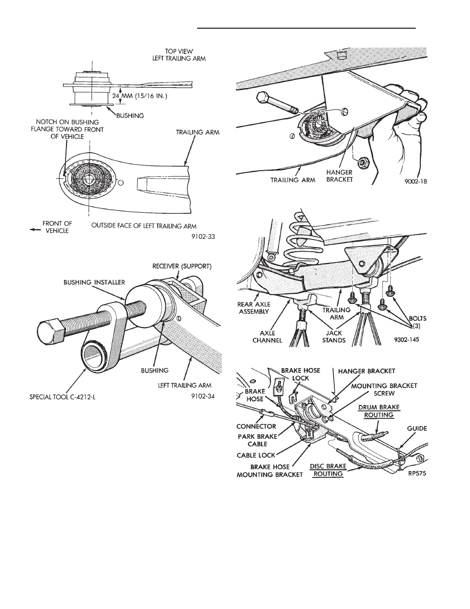
Fig. 9 Proper Position of Pivot Bushing
Fig. 10 Tools Assembled for Bushing Installation
Fig. 11 Install Hanger Bracket to Pivot Bushing
Fig. 12 Install Hanger Bracket on Frame
Fig. 13 Brake Hose Bracket & Park Brake Cable
2 - 54
SUSPENSION AND DRIVESHAFTS
Ä

PIVOT BUSHING AC AG AJ AP BODY
REMOVE FROM VEHICLE
(1) Raise vehicle (see Hoisting, Group 0). Remove
brake hose mounting bracket screw (Fig. 1).
(2) Detach park brake cable at connector and from
hanger bracket (Fig. 1).
WARNING: WHEN REMOVING THE REAR AXLE
PIVOT BUSHING ON VEHICLES EQUIPPED WITH EI-
THER REAR COIL SPRINGS OR AIR SUSPENSION.
THE REAR AXLE MUST BE SUPPORTED BY THE
AXLE AND TRAILING ARM TO ENSURE ADEQUATE
SUPPORT OF REAR AXLE.
(3) Support the rear axle assembly at both the axle
channel and the trailing arm with jack stands (Fig.
2). Then remove lower shock absorber to rear axle
mounting bolt (Fig. 2).
(4) Remove hanger bracket to frame rail bolts (Fig.
3).
(5) Lower axle assembly down enough to remove
pivot bolt and hanger bracket (Fig. 3). Right side
trailing arm shown.
PIVOT BUSHING REMOVAL FROM AXLE AS-
SEMBLY
Remove bushing with Remover/Installer Spe-
cial Tool C-4702-7 Press. And 3 piece set, Special
Tool C-4212 and C-4366-1 (Receiver Support
Bridge, Bushing Remover/Installer and Bushing
Remover).
(1) Install receiver (support) cup C-4366-1 into base
of press C-4212 and Bushing Remover Cup C-4702-7
onto screw.
(2) Position assembly with receiver bridge support-
ing trailing arm while turning screw to begin bushing
removal.
(3) After bushing has begun to move replace bushing
remover/installer (round disc) with bushing remover
(oval shaped disc). Use this assembly to finish pressing
bushing out of trailing arm (Fig. 4).
PIVOT BUSHING INSTALLATION
(1) Align the bushing with the bushing mounting
hole in the trailing arm bracket (Fig. 5). Tap bushing in
slightly to hold it in position on trailing arm.
(2) Assemble
Bushing
Installer
Special
Tool
C-4702-2 onto press screw and Support Cup Special
Fig. 1 Remove Brake Hose Mounting Bracket Screw
and Park Brake Cable
Fig. 2 Remove Pivot Bushing Hanger Bracket Bolts
Fig. 3 Remove Hanger Bracket
Fig. 4 Tools Installed To Remove Bushing
Ä
SUSPENSION AND DRIVESHAFTS
2 - 55
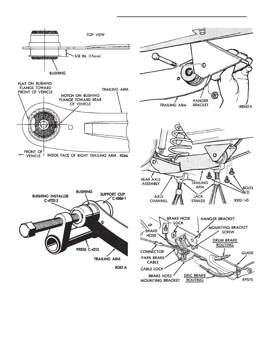
Tool C-4366-1 into press base. Position assembly as
shown in (Fig. 6) and press bushing into arm to
depth shown in (Fig. 5).
(3) Position hanger bracket on pivot bushing, and
install through bolt, loose assemble nut (Fig. 7). Right
side trailing arm shown.
(4) Position hanger to frame rail (a suitable drift will
aid in guiding hanger bracket into position). Install
and tighten screws to 75 N
Im (55 ft. lbs.) torque (Fig.
8). Install lower shock absorber mounting bolt, but do
not tighten.
(5) Position brake hose mounting bracket to trailing
arm, install and tighten retaining screw to 11 N
Im (95
in. lbs.) torque (Fig. 9).
(6) Attach park brake cable housing to hanger
bracket and cable to connector.
(7) Lower vehicle with suspension supporting vehi-
cle weight, trailing arm at design height. Tighten
pivot bolt nut and lower shock absorber mounting
bolt to 61 N
Im (45 ft. lbs.) torque.
Fig. 7 Install Hanger Bracket to Pivot Bushing
Fig. 8 Install Hanger Bracket on Frame
Fig. 9 Brake Hose Bracket & Park Brake Cable
Fig. 5 Proper Position of Pivot Bushing
Fig. 6 Tools Assembled for Bushing Installation
2 - 56
SUSPENSION AND DRIVESHAFTS
Ä
REAR AXLE ASSEMBLY
REMOVE
(1) Raise vehicle (see Hoisting, Group 0). Support
axle with jack stands and remove wheel and tire as-
sembly.
(2) Separate park brake cable at connector. Detach
cable housing from hanger bracket (Fig. 1).
(3) Remove lock and separate brake tube assembly
from brake hose mounting bracket (Fig. 1).
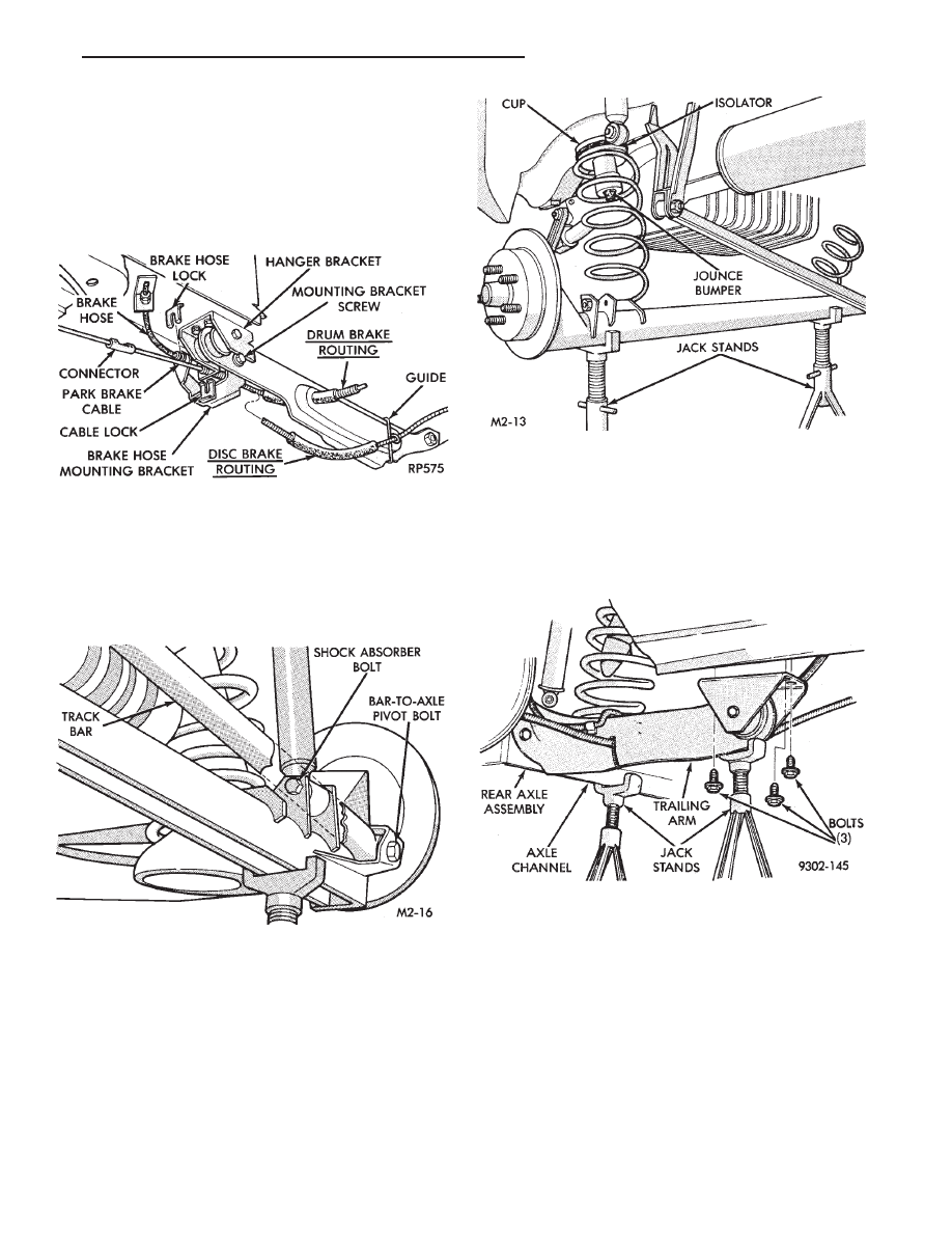
(4) Remove lower shock absorber through bolts and
track bar to axle pivot bolt. Support track bar end
with wire (Fig. 2).
(5) Lower axle until spring and isolator assemblies
can be removed. Remove spring and isolator assem-
blies (Fig. 3).
(6) Support pivot bushing end of the trailing arms.
(as well as axle beam with jack stands) Remove pivot
bushing hanger bracket to frame screws. Lower and
remove axle assembly from vehicle.
(7) Remove rear brake assemblies, see Group 5 for
proper procedure.
(8) For pivot bushing removal and installation see
PIVOT BUSHING this group.
INSTALLATION
(1) Raise and support axle on jack stands.
(2) Attach pivot bushing hanger brackets to frame
rail (Fig. 4). Tighten screws to 61 N
Im (45 ft. lbs.)
torque.
(3) Install springs and isolators (Fig. 5).
(4) Raise axle and install shock absorber and track
bar through bolts loose assemble only (Fig. 6).
(5) Install brake assembly as follows:
DRUM BRAKE ASSEMBLY
(1) Position spindle, seal, and brake support to
axle after routing park brake cable through trailing
arm opening and brake tube over arm (Figs. 1). In-
stall the 4 spindle mounting bolts finger tight. Then
torque the 4 spindle mounting bolts to 75 N
Im (55 ft.
lbs.) torque.
(2) Install brake drum and bearings.
Fig. 1 Remove Brake Hose Mounting Bracket Screw
and Park Brake Cable
Fig. 2 Remove Shock Absorber and Track Bar Bolts
Fig. 3 Remove/Install Coil Spring and Isolator
Assembly
Fig. 4 Attach Hanger Brackets to Frame
Ä
SUSPENSION AND DRIVESHAFTS
2 - 57
Нет комментариевНе стесняйтесь поделиться с нами вашим ценным мнением.
Текст