Chrysler Le Baron, Dodge Dynasty, Plymouth Acclaim. Manual — part 255

MASTER CYLINDER AND POWER BOOSTER
REMOVAL AND INSTALLATION
If the Master Cylinder or Power Booster need to be
removed for replacement or servicing of other vehicle
components. Refer to Master Cylinder or Power
Brake Service section in group 5 of the 1993 M.Y.
Front Wheel Drive Car service manual.
After servicing master cylinder, refer back to this
service manual supplement for the appropriate proce-
dure and sequence used to bleed the base and Anti-
lock portion of the brake system.
PROPORTIONING VALVES (FIG. 1)
CAUTION: Proportioning valves should never be
disassembled.
REMOVAL
(1) Disconnect and remove both battery cables
from battery.
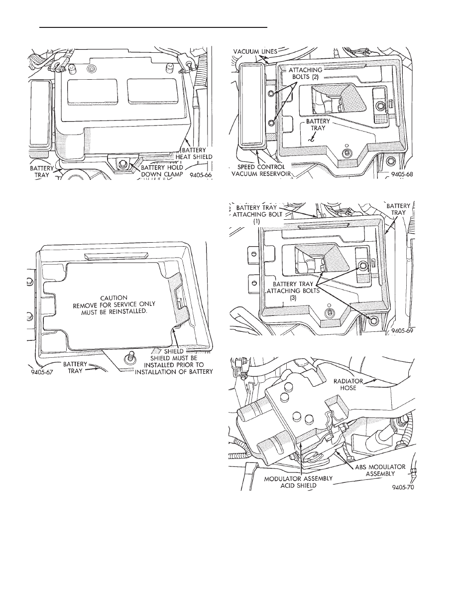
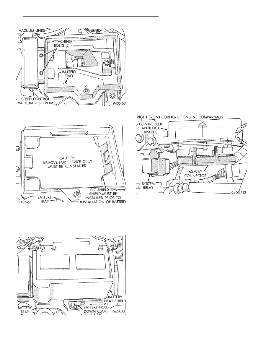
(2) Remove heat shield (Fig. 2) from the battery.
Then remove battery hold down clamp (Fig. 2) and
battery from battery tray.
Fig. 15 Battery Tray Installation And Attaching Bolts
Fig. 16 Vacuum Reservoir Installation And
Attaching Bolts
Fig. 17 Battery Tray Access Shield Installed
Fig. 18 Battery Hold Down Clamp And Heat Shield
Installed
Fig. 1 ABS Proportioning Valve Identification
5 - 38
ANTILOCK 4 BRAKE SYSTEM
Ä
(3) Remove battery tray access cover (Fig. 3) from
battery tray. Do not discard, access cover MUST be
put back on battery tray, when battery is rein-
stalled.
(4) If equipped, remove the 2 bolts (Fig. 4) attaching
speed control vacuum reservoir to battery tray. Then
remove speed control vacuum reservoir (Fig. 4) from
the battery tray. Vacuum lines (Fig. 4) do not need
to be removed from vacuum reservoir.
(5) Remove the 4 bolts attaching battery tray (Fig. 5)
to frame rail and fender shield of vehicle. Then remove
battery tray from vehicle.
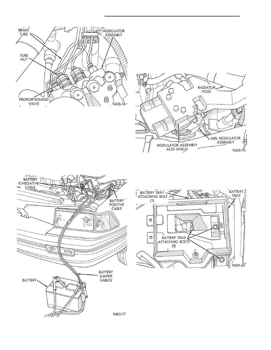
(6) Remove battery acid shield, (Fig. 6) from the ABS
modulator assembly.
(7) Remove brake tube from the proportioning valve,
requiring removal from modulator assembly (Fig. 7).
(8) Remove proportioning valve (Fig. 7) requiring
replacement from the modulator assembly.
INSTALL
(1) Slightly moisten proportioning valve to modulator
assembly sealing O-Ring with fresh clean brake fluid.
(2) Install proportioning valve into modulator as-
sembly by hand, until O-Ring seal is fully seated
Fig. 4 Speed Control System Vacuum Reservoir
Fig. 5 Battery Tray And Attaching Bolts
Fig. 6 ABS Modulator Assembly Acid Shield
Fig. 2 Battery Heat Shield And Hold Down Clamp
Fig. 3 Battery Tray Shield
Ä
ANTILOCK 4 BRAKE SYSTEM
5 - 39
against modulator assembly. Then torque proportion-
ing valve to 35 N
Im (26 ft. lbs.) torque.
(3) Install hydraulic brake line on proportioning
valve and hand start tube nut into proportioning valve.
Torque tube nut to 18 N
Im (159 in. lbs.) torque.
(4) Using approved battery jumper cables, attach
battery, to the vehicles negative and positive battery
cables (Fig. 8).
(5) Bleed the vehicles base brake and Antilock brake
hydraulic systems. Refer to Bleeding Bendix Antilock 4
Brake System in this service manual supplement for
required bleeding procedure.
(6) Install battery acid shield (Fig. 9) onto the ABS
modulator assembly. Be sure acid shield is securely
attached to modulator assembly before installing
battery tray.
(7) Install battery tray in vehicle. Then install the 4
bolts (Fig. 10) attaching battery tray to inner fender
and frame rail. Torque the 4 battery tray attaching
bolts to 20 N
Im (175 in.lbs.).
(8) If equipped, install speed control vacuum reser-
voir on battery tray. Install the 2 speed control vacuum
reservoir attaching bolts (Fig. 11). Torque the 2
vacuum reservoir attaching bolts to 4 N
Im (30 in. lbs.).
(9) Install battery tray access cover (Fig. 12) on
bottom of battery tray. The access cover MUST be
on battery tray, before battery is installed in
battery tray.
Fig. 8 Battery Connected To Vehicle For Bleeding
Modulator Assembly
Fig. 7 Proportioning Valve Removal From Modulator
Assembly
Fig. 9 Modulator Assembly Acid Shield Installed
Fig. 10 Battery Tray Installation And Attaching Bolts
5 - 40
ANTILOCK 4 BRAKE SYSTEM
Ä
(10) Install battery on battery tray and install and
securely tighten the battery hold down clamp (Fig.
13). Then install heat shield, on battery (Fig. 13).
(11) Install battery cables on battery. Securely
tighten clamping bolts on battery cable terminals.
(12) Reset any electrical components of the vehicle
which were affected by the removal of the battery.
(13) Road test vehicle to verify correct operation of
the vehicles’s base and Antilock brake systems.
ELECTRONIC COMPONENTS
CONTROLLER ANTILOCK BRAKE CAB
REMOVE
(1) Turn vehicle ignition off.
(2) Disconnect the wiring harness connector from
the Antilock system relay (Fig. 1). Relay will be re-
moved as part of the CAB bracket.
CAUTION: BEFORE REMOVING 60 WAY CONNEC-
TOR FROM THE CAB VERIFY THAT THE VEHICLE’S
IGNITION IS IN THE OFF OR LOCK POSITION. IF IG-
NITION IS ON WHEN 60 WAY CONNECTOR IS RE-
MOVED
FROM
THE
CAB
DAMAGE
TO
THE
CONTROLLER COULD OCCUR.
(3) Loosen bolt (Fig. 2) retaining the wiring har-
ness 60 way connector to the CAB. Then disconnect
the 60 way connector (Fig. 2) from the CAB by pull-
ing it straight out, do not twist connector when re-
moving.
(4) Remove the 2 bolts (Fig. 3) attaching the CAB
module mounting bracket, to the frame rail of the ve-
hicle.
(5) Remove the CAB and its mounting bracket as
an assembly from the vehicle from the vehicle.
(6) Remove the 3 screws (Fig. 4) attaching the
CAB to the CAB mounting bracket. Then separate
CAB from mounting bracket.
Fig. 11 Vacuum Reservoir Installation And
Attaching Bolts
Fig. 12 Battery Tray Access Shield Installed
Fig. 13 Battery Hold Down Clamp And Heat Shield
Installed
Fig. 1 CAB Location
Ä
ANTILOCK 4 BRAKE SYSTEM
5 - 41
Нет комментариевНе стесняйтесь поделиться с нами вашим ценным мнением.
Текст