Chrysler Le Baron, Dodge Dynasty, Plymouth Acclaim. Manual — part 569
CAUTION: Make sure clutch cable has been discon-
nected.
(20) Remove front engine mount screw and nut.
(21) Remove manual transmission damper.
(22) Remove left insulator through bolt from inside
wheelhouse or insulator bracket to transmission
screws.
(23) Remove engine from vehicle.
INSTALLATION
(1) Install hoist to the engine and lower engine
into the engine compartment.
SEE: ENGINE MOUNT RUBBER INSULATORS,
THIS GROUP.
(2) Align engine mounts and install but do not
tighten until all mounting bolts have been installed.
(3) Install transmission case to cylinder block
mounting screws. Tighten to 95 N
Im (70 ft. lbs.)
torque.
(4) Remove engine hoist and transmission holding
fixture.
(5) Install ground strap.
(6) Install right inner splash shield.
(7) Connect starter. See Electrical Group 8 for in-
stallation.
(8) Connect exhaust system. See Exhaust Systems
Group 11 for installation.
(9) Manual Transmission: Install transmission
case lower cover.
Automatic Transmission: Remove C clamp from
torque converter housing. Align flexplate to torque
converter and install mounting screws. Tighten to 75
N
Im (55 ft. lbs.) torque.
(10) Manual Transmission: Connect clutch cable.
See Clutch Group 6.
(11) Install power steering pump. Refer to Cooling
System Group 7, Accessory Drive Section for belt
tension adjustment.
(12) Connect fuel line, heater hose, and accelerator
cable.
(13) Connect all electrical connections and har-
nesses at throttle body and engine.
(14) Install oil filter. Fill engine crankcase with
proper oil to correct level.
(15) Install
air
conditioning
compressor
(if
equipped). See Heater and Air Conditioning, Group
24 for installation.
(16) Install air cleaner and hoses.
(17) Install radiator and shroud assembly . Install
radiator hoses. Fill cooling system. See Cooling Sys-
tem Group 7 for filling procedure.
(18) Install hood.
(19) Connect battery.
(20) Start engine and run until operating temper-
ature is reached.
(21) Adjust transmission linkage, if necessary.
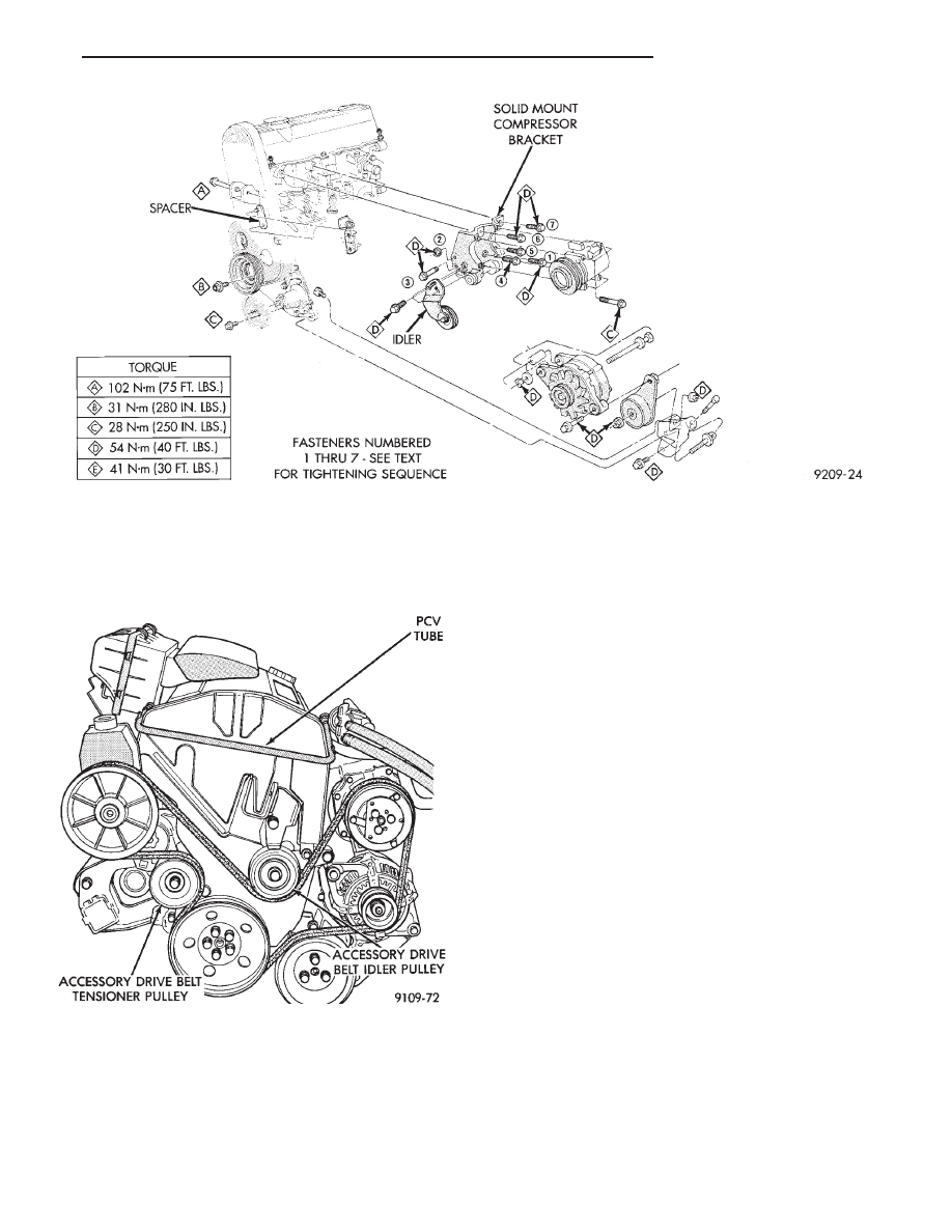
SOLID MOUNT COMPRESSOR BRACKET SERVICE
When
service
procedures
require
solid
mount
bracket removal and installation for example: cylin-
der head removal, etc., it is important that bracket
fasteners numbered 1 through 7 (Fig. 4) be removed
and installed in sequence, as instructed in Remove
and Install.
ACCESSORIES REMOVAL
(1) Remove (and install/adjust) belts,see Accessory
Drive Belts in Cooling System,Group 7.
(2) Remove air conditioning compressor (in vehicle
with lines and set aside) (Fig. 6).
(3) Remove generator pivot bolt and remove gener-
ator (in vehicle: turn wiring side up and disconnect,
then rotate generator, pulley end towards engine and
remove).
(4) Remove air conditioner compressor belt idler.
SOLID MOUNT BRACKET—REMOVAL (FIG. 4)
(1) Remove right engine mount yoke screw (see
Engine Remove Fig. 3) securing engine mount sup-
port strut to engine mount bracket.
(2) Remove five side mounting bolts #1, #4 , #5,
#6, and #7 (Fig. 4).
(3) Remove front mounting nut, #2, and remove
front bolt #3*.
(4) Remove front mounting bolt and strut, rotate
solid mount bracket away from engine and slide
bracket on stud until #2 nut mounting stud until
free. Remove spacer from stud.
SOLID MOUNT BRACKET—INSTALLATION
(1) Put spacer onto stud, then install bracket on
front (#2 nut) mounting stud and slide bracket over
timing belt cover into position.
(2) Loosen assembly bracket to engine fasteners
(numbered #1 through #7 in Fig. 6).
(3)
CAUTION: Fasteners MUST BE TIGHTENED IN SE-
QUENCE and to specified torque as follows :
• First Bolt #1 to 3.3 NIm (30 in. lbs.)
• Second Nut #2 and Bolt #3 to 54 NIm (40 ft. lbs.).
• Third Bolts #1 (second tightening) #4 and #5 to
54 N
Im (40 ft. lbs.).
• Fourth Bolts #6 and #7 to 54 NIm (40 ft. lbs.).
(4) Install generator and compressor. Tighten com-
pressor mounting bracket bolts to 54 N
Im (40 ft.
lbs.).
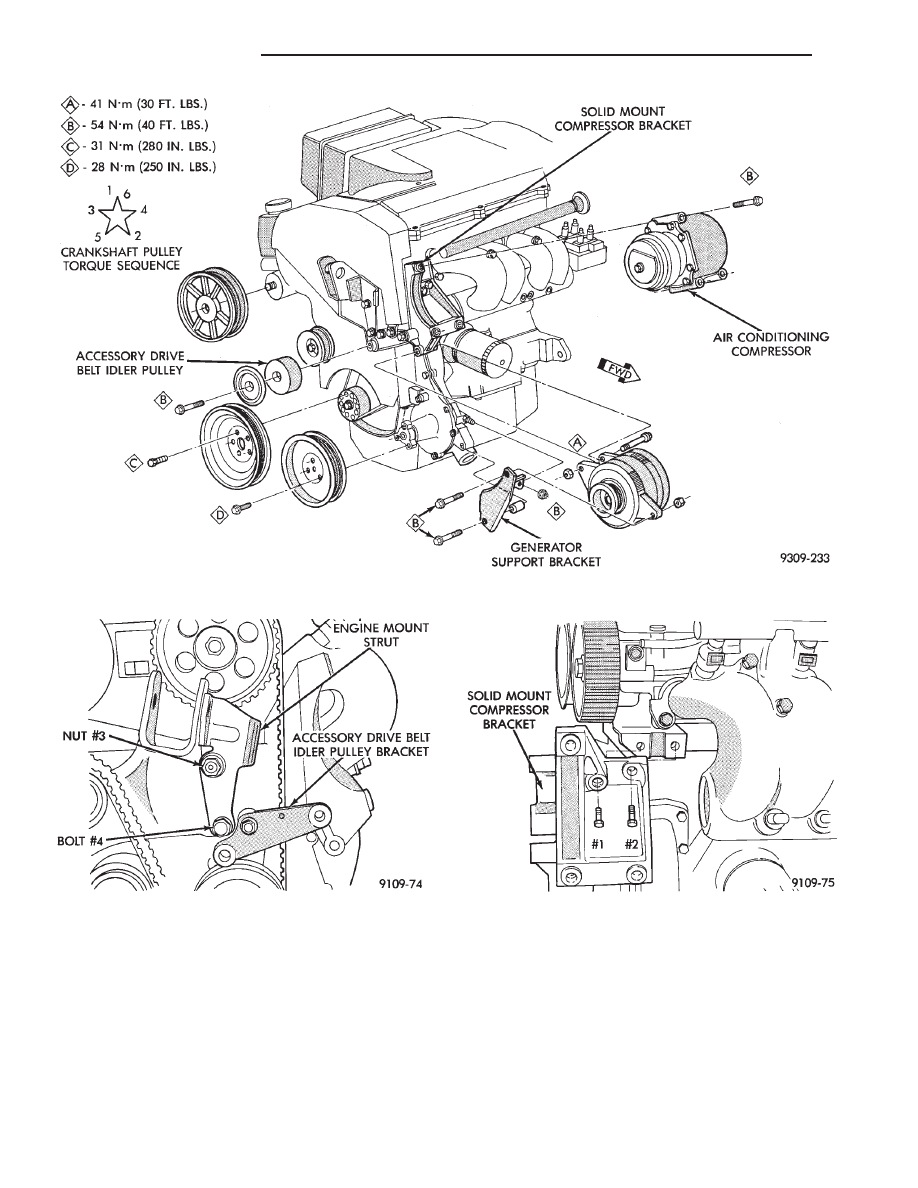
SOLID MOUNT COMPRESSOR BRACKET
SERVICE—TURBO III ENGINE
REMOVAL
(1) Disconnect negative battery cable
9 - 14
2.2/2.5L ENGINE
Ä
(2) Remove Accessory Drive Belt. Refer to Cooling
System Group 7 for procedure.
(3) Remove accessory drive belt idler pulley (Fig.
7).
(4) Remove air conditioning compressor and set
aside (Fig. 8).
(5) Remove generator attaching bolts set aside
(Fig. 8).
(6) Remove timing belt covers. Refer to procedure
outlined in this section.
(7) Remove right engine mount yoke bolt. Remove
the fasteners holding the strut into place. Remove
strut from engine (Fig. 9).
(8) Remove
accessory
drive
belt
idler
pulley
bracket (Fig. 9).
(9) Remove timing belt. Refer to procedure out-
lined in this section.
(10) Remove 2 bolts holding solid mount compres-
sor into place, Rotate bracket off engine (Fig. 7).
INSTALLATION
(1) Loosely assemble the bracket to engine with #1
and #2 bolts tighten to 3.3 N
Im (30 in. lbs.) (Fig. 8).
(2) Install timing belt. Refer to procedure outlined
in this section. Install timing belt covers. Refer to
procedure outlined in this section.
(3) Install strut on stud. Tighten nut #3 and bolt
#4, torque to 54 N
Im (40 ft. lbs.) (Fig. 9). Loosen #1
and #2 bolts, then torque to 54 N
Im (40 ft. lbs.) (Fig.
10).Install yoke bolt and torque to 102 N
Im (75 ft.
lbs.).
(4) Install accessory drive belt idler pulley and
bracket (Fig. 8).
(5) Install accessory drive belt tensioner pulley
(Fig. 7).
(6) Install generator (Fig. 8).
(7) Install air conditioning compressor (Fig. 8).
(8) Install accessory drive belt. Refer to Cooling
System Group 7 for procedure.
(9) Connect negative battery cable.
Fig. 6 Solid Mount Compressor Bracket 2.2 & 2.5L Engines
Fig. 7 Accessory Drive System
Ä
2.2/2.5L ENGINE
9 - 15
POWER STEERING/ACCESSORY DRIVE BELT
TENSIONER BRACKET
REMOVAL
(1) Remove Accessory Drive Belt. Refer to Cooling
System Group 7 for procedure.
(2) Remove accessory drive belt tensioner pulley
(Fig. 7).
(3) Remove Timing Belt covers. Refer to procedure
outlined in this section.
(4) Remove Power Steering Pump bolts set pump
aside (Fig. 11).
(5) Loosen timing belt tension. Refer to Camshaft
and Crankshaft Timing Service for procedure. Re-
move timing belt idler pulley bolt (Fig. 12).
CAUTION: Camshaft and Crankshaft Timing may
have to be reset when procedure is completed Refer
to procedure outlined in this section.
Fig. 8 Solid Mount Compressor Bracket—Turbo III Engine
Fig. 9 Accessory Drive Idler Pulley Bracket and
Engine Strut
Fig. 10 Compressor Bracket to Cylinder Head
Attaching Bolts
9 - 16
2.2/2.5L ENGINE
Ä
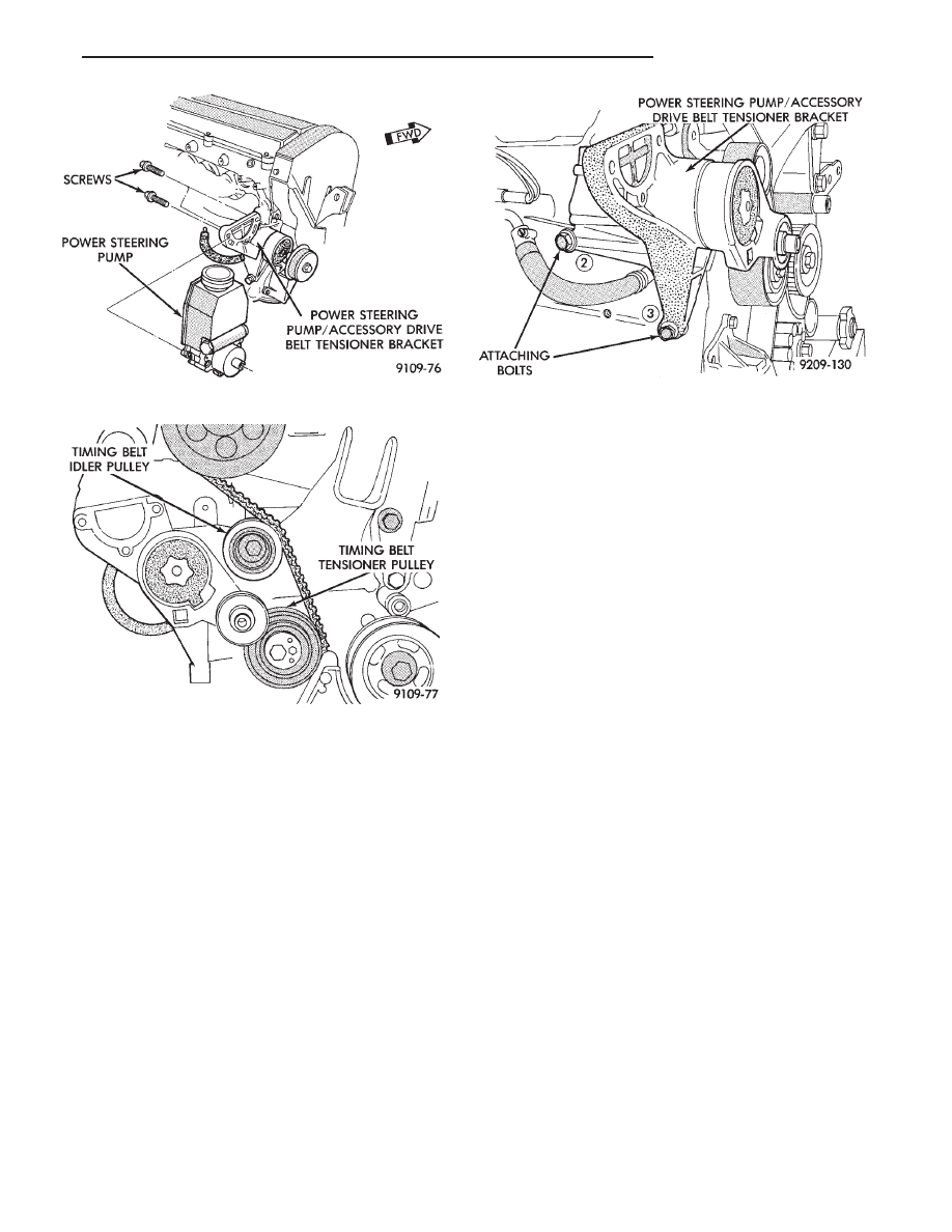
(6) Remove Bracket bolts #2 and #3 from rear of
engine. Remove Bracket (Fig. 13).
INSTALLATION
(1) Loose assemble bracket to engine.
(2) Tighten bolts #2 and #3 to 3.3 N
Im (30 in. lbs.)
(Fig. 13).
(3) Tighten timing belt idler pulley and tighten to
54 N
Im (40 ft. lbs.) (Fig. 12).
(4) Tighten bolts 32 and #3 to 54 N
Im (40 ft. lbs.)
(Fig. 13).
(5) Camshaft and Crankshaft timing should be
checked at this time.
Adjust as necessary following procedure outlined in
this section.
(6) Install power steering pump on bracket tighten
bolts to 28 N
Im (250 in. lbs.) torque (Fig. 11).
(7) Install timing belt covers. Refer to procedure
outlined in this section.
CAUTION: Do not use impact wrench on accessory
drive belt tensioner bolt. It may cause damage to
tensioner arm.
(8) Install accessory drive belt tensioner pulley
bolt finger tight. Then tighten bolt to 54 N
Im (40 ft.
lbs.) torque. Install accessory drive belt, Refer to
Cooling System Group 7 for procedure.
Fig. 11 Power Steering Pump Attaching Bolts
Fig. 12 Power Steering Pump Bracket and Timing
Belt Idler Bolt
Fig. 13 Power Steering Pump/Accessory Drive Belt
Tensioner Bracket Attaching Bolts
Ä
2.2/2.5L ENGINE
9 - 17
Нет комментариевНе стесняйтесь поделиться с нами вашим ценным мнением.
Текст