Chrysler Le Baron, Dodge Dynasty, Plymouth Acclaim. Manual — part 570
TIMING SYSTEM AND SEALS SERVICE—EXCEPT TURBO III
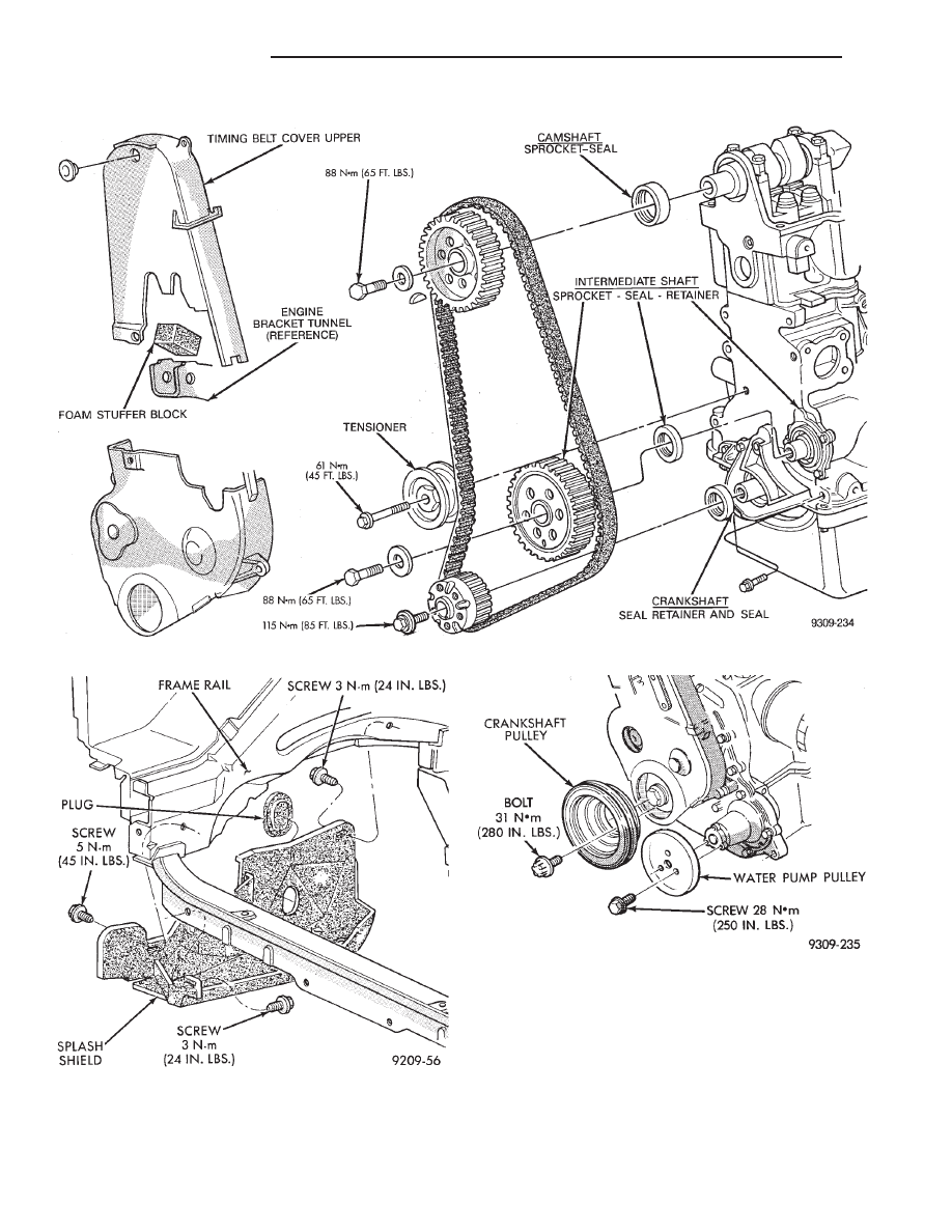
Refer to (Fig. 1) for parts identification and torque
specifications
TIMING BELT SERVICE
(1) Remove Solid Mount Compressor Bracket. Re-
fer to procedure outlined in this section.
(2) Raise vehicle on a hoist and remove right inner
splash shield (Fig. 2).
(3) Remove screws retaining water pump pulley
and bolts retaining crankshaft pulley (Fig. 3) and lay
pullies aside.
(4) Remove nuts holding cover to cylinder head.
Fig. 2 Right Inner Splash Shield
Fig. 3 Crankshaft and Water Pump Pulley
Fig. 1 Timing System and Seals
9 - 18
2.2/2.5L ENGINE
Ä

(5) Remove screws holding cover to cylinder block.
(6) Remove both halves of timing belt cover and
lay aside (Fig. 4)
(7) Place a jack under engine.
(8) Separate right engine mount (Fig. 5) and raise
engine slightly.
(9) Loosen timing belt tensioner screw (Fig. 6) and
remove timing belt.
SERVICING FRONT OIL
SEALS—REPLACEMENT
(1) With timing belt removed, remove crankshaft
sprocket bolt.
(2) Remove crankshaft sprocket using Special Tool
C-4685, Insert and 5.9 inch long screw (Fig. 7).
(3) Install crankshaft sprocket using plate L-4524,
Thrust Bearing/washer and 5.9 inch long screw (Fig.
7).
Fig. 4 Timing Belt Cover
Fig. 7 Crankshaft Sprocket
Fig. 5 Right Engine Mount
Fig. 6 Remove Timing Belt
Ä
2.2/2.5L ENGINE
9 - 19
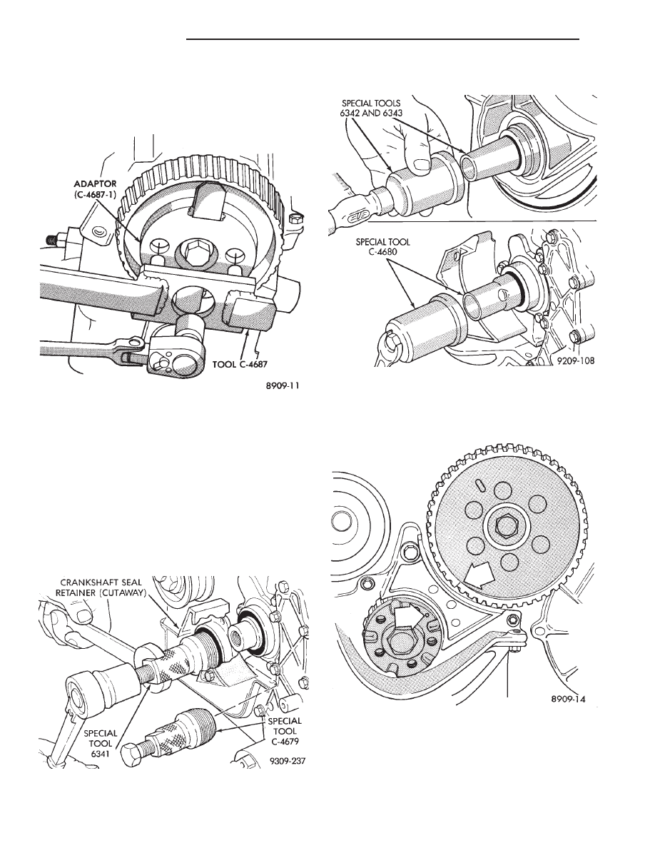
(4) Hold engine sprocket with Special Tool C-4687
(with adaptor Tool C-4687-1) while removing/install-
ing screw (Fig. 8). The 2.5L Engine camshaft/inter-
mediate shaft sprockets have an off-set hub and are
identified with a six-hole pattern .
(5) Remove crankshaft seal using Special Tool
6341. Remove intermediate and camshaft seals using
Special Tool C-4679 (Fig. 10).
CAUTION: Do not nick shaft seal surface or seal
bore.
(6) Shaft seal lip surface must be free of varnish,
dirt or nicks. Polish with 400 grit paper if necessary.
(7) Install engine crankshaft seal into retainer us-
ing Special Tool 6342 and 6343. Install Intermediate
and Camshaft seals using Special Tool C-4680. In-
stall seals until flush (Fig. 10).
CAMSHAFT, CRANKSHAFT AND INTERMEDIATE
SHAFTS TIMING PROCEDURE
(1) Remove all spark plugs. Turn crankshaft and
intermediate shaft until markings on sprockets are
in line, see arrows (Fig. 11 ).
Fig. 9 Removing Crankshaft, Intermediate Shaft and
Camshaft Oil Seal
Fig. 8 Removing/Installing Camshaft or Intermediate
Shaft Sprocket Screw
Fig. 10 Installing Crankshaft,Intermediate Shaft, and
Camshaft Seal
Fig. 11 Crankshaft and Intermediate Shaft Timing
9 - 20
2.2/2.5L ENGINE
Ä

(2) Turn camshaft until arrows on hub are inline
with No. 1 camshaft cap to cylinder headline. Small
hole (arrow Fig. 12) must be in vertical center line.
(3) Install timing belt.
(4) Rotate crankshaft two full revolutions and re-
check timing.
CAUTION: Do not allow oil or solvents to contact
the timing belt as they can deteriorate the rubber
and cause tooth skipping.
(5) Rotate crankshaft till number 1 cylinder is at
the TDC position.
(6) Put belt tension Special Tool C-4703 horizon-
tally on large hex of timing belt tensioner pulley and
loosen tensioner lock nut.
(7) Reset belt tension Special Tool C-4703 index if
necessary to have axis within 15° of horizontal. (Fig.
13)
(8) Turn engine clockwise from TDC two crank revo-
lutions to TDC. Do not reverse rotate crankshaft
or attempt to rotate engine using cam or acces-
sory shaft attaching screw.
(9) Hold weighted wrench in position while tighten-
ing bolt on tensioner to 61 N
Im (45 ft. lbs.) torque.
(10) Lower engine onto engine mount install mount-
ing bolts and tighten to specifications refer to (Fig. 3).
(11) Remove jack from under engine.
(12) Inspect foam stuffer block condition and posi-
tion (Fig. 14). Stuffer block should be intact and secure
within the engine bracket tunnel.
(13) Position both halves of timing belt cover to-
gether (Fig. 4).
(14) Install fasteners holding cover to cylinder head
and block. Tighten fasteners to 4 N
Im (40 in. lbs.)
torque.
(15) Valve Timing Check; (timing belt cover in-
stalled). With number one cylinder at TDC, small hole
in sprocket must be centered in timing belt cover hole
(Fig. 12). If hole is not aligned correctly perform
procedure again.
(16) Install spark plugs.
Fig. 12 Camshaft Timing
Fig. 13 Adjusting Drive Belt Tension
Fig. 14 Foam Stuffer Block Location
Ä
2.2/2.5L ENGINE
9 - 21
Нет комментариевНе стесняйтесь поделиться с нами вашим ценным мнением.
Текст