Chrysler Le Baron, Dodge Dynasty, Plymouth Acclaim. Manual — part 134
(a) Attach Tool L-4432 to the gear.
(b) Push and pull the gear while rotating back
and forth to insure seating of the bearing rollers.
(c) Using a dial indicator, mounted to the tran-
saxle case, measure output gear end play.
(4) Once bearing end play has been determined, re-
fer to the output gear bearing shim chart for the re-
quired shim to obtain proper bearing setting.
(5) Use Tool 6259 to remove the retaining bolt and
washer. To remove the output gear, use Tool L-4407.
(6) Remove the gauging shim and install the
proper shim. Use grease to hold the shim in place.
Install the output gear and bearing assembly.
CAUTION: Always use new retaining bolt, old re-
taining bolt may not be reused.
(7) Install the new retaining bolt and washer.
Tighten to 271 N
Im (200 ft. lbs.).
(8) Using an inch-pound torque wrench, check the
turning torque. The torque should be between 3
and 8 inch-pounds.
If the turning torque is too high, install a .04 mm
(.0016 inch) thicker shim. If the turning torque is too
low, install a .04 mm (.0016 inch) thinner shim. Re-
peat until the proper turning torque is 3 to 8 inch
pounds.
DIFFERENTIAL BEARING
(1) Remove the bearing cup from the differential
bearing retainer using Tool L-4518, and remove the
existing shim from under the cup.
(2) Install a .50 mm (.020 inch) gauging shim and
reinstall the bearing cup into the retainer. Use an
arbor press to install the cup.
Oil Baffle is not required when making shim
selection.
(3) Install the bearing retainer into the case and
torque bolts to 28 N
Im (250 in. lbs.).
(4) Position the transaxle assembly vertically on the
support stand and install Tool C-4995 into side gear.
(5) Rotate the differential at least one full revolution
to ensure the tapered roller bearings are fully seated.
(6) Attach a dial indicator to the case and zero the
dial indicator. Place the indicator tip on the end of Tool
L-4436.
(7) Place a large screwdriver to each side of the ring
gear and lift. Check the dial indicator for the amount of
end play.
CAUTION: Do not damage the transaxle case and/or
differential cover sealing surface.
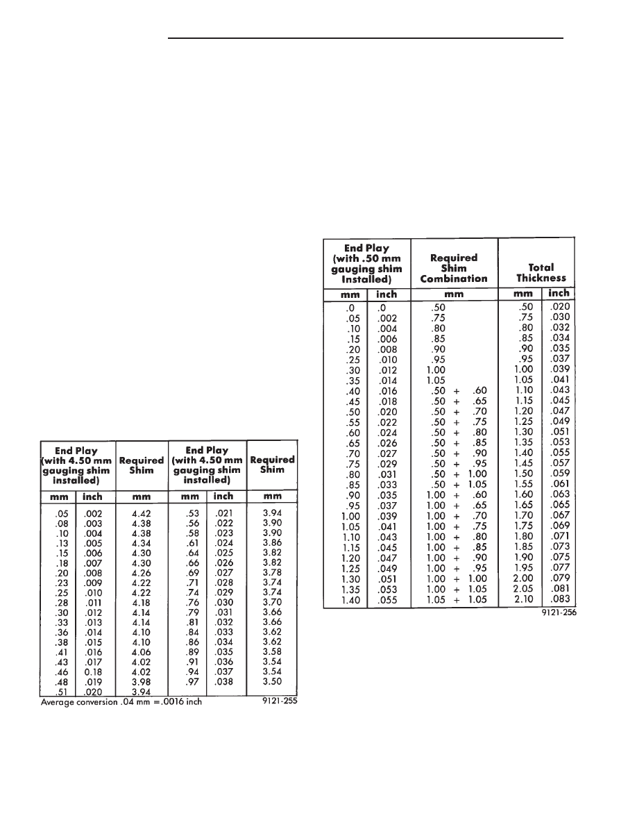
OUTPUT GEAR BEARING SHIM CHART
DIFFERENTIAL BEARING SHIM CHART
21 - 142
TRANSAXLE
Ä
(8) When the end play has been determined, refer to
the Differential Bearing Shim Chart for the correct
shim combination to obtain the proper bearing setting.
(9) Remove the differential bearing retainer. Re-
move the bearing cup and the .50 mm (.020 inch)
gauging shim.
(10) Install the proper shim combination under the
bearing cup. Make sure the oil baffle is installed
properly in the bearing retainer, below the bearing
shim and cup.
(11) Install the differential bearing retainer. Seal
the retainer to the housing with MOPAR
t Adhesive
Sealant and torque bolts to 28 N
Im (250 in. lbs.).
(12) Using Tool C-4995 and an inch-pound torque
wrench, check the turning torque of the differential.
The turning torque should be between 5 and 18
inch-pounds.
If the turning torque is too high, install a .05
mm (.002 inch) thinner shim. If the turning
torque is too low, install a .05 mm (.002 inch)
thicker shim. Repeat until 5 to 18 inch-pounds
turning torque is obtained.
TRANSFER SHAFT BEARING
(1) Use Tool 6259 to remove the retaining nut and
washer. Remove the transfer shaft gear using Tool
L-4407.
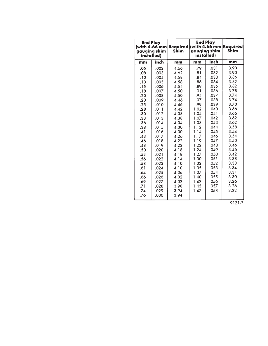
(2) Install a 4.66 mm (.184 inch) gauging shim on the
transfer shaft.
(3) Install transfer shaft gear and bearing assembly
and torque the nut to 271 N
Im (200 ft. lbs.).
(4) To measure bearing end play:
(a) Attach Tool L-4432 to the transfer gear.
(b) Mount a steel ball with grease into the end of
the transfer shaft.
(c) Push and pull the gear while rotating back and
forth to insure seating of the bearing rollers.
(d) Using a dial indicator, measure transfer shaft
end play.
(5) Refer to the Transfer Bearing Shim Chart for the
required shim combination to obtain the proper bear-
ing setting.
(6) Use Tool 6259 to remove the retaining nut and
washer. Remove the transfer shaft gear using Tool
L-4407.
(7) Remove the gauging shim and install the correct
shim. Install the transfer gear and bearing assembly.
CAUTION: Original retaining nut may not be re-
used. Always use a new retaining nut when reassem-
bling.
(8) Install the new retaining nut and washer and
torque to 271 N
Im (200 ft. lbs.). Measure transfer
shaft end play, end play should be .05 to .10 mm
(.002 to .004 inch).
(9) Measure bearing end play as outlined in Step (4).
End play should be between .05 mm and .10 mm (.002
to .004 inch).
If end play is too high, install a .04 mm (.0016
inch) thinner shim. If end play is too low, install
a .04 mm (.0016 inch) thicker shim combination.
Repeat until .05 to .10 mm (.002 to .004 inch) end
play is obtained.
TRANSFER BEARING SHIM CHART
Ä
TRANSAXLE
21 - 143

BEARING SHIM CHART
21 - 144
TRANSAXLE
Ä
41TE ON-BOARD DIAGNOSTICS
INDEX
page
page
CCD Bus
. . . . . . . . . . . . . . . . . . . . . . . . . . . . . . 145
Diagnostic Trouble Code Charts
. . . . . . . . . . . . 146
Diagnostic Trouble Codes
. . . . . . . . . . . . . . . . . 145
DRB II Scan Tool
. . . . . . . . . . . . . . . . . . . . . . . 146
General Information
. . . . . . . . . . . . . . . . . . . . . . 145
Limp-In Mode
. . . . . . . . . . . . . . . . . . . . . . . . . . 145
On-Board Diagnostics Information
. . . . . . . . . . . 145
GENERAL INFORMATION
The information in this manual is designed to help
the technician understand and repair the transaxle
with the aid of the built in on-board diagnostics.
Chrysler Corporation has developed a com-
plete set of diagnostic manuals which cover the
diagnosis of the 41TE transaxle. They have been
designed to make transaxle diagnosis accurate
and simple. Use these manuals with the DRB II
scan tool and the latest cartridge, when diagnos-
ing transaxle problems.
ON-BOARD DIAGNOSTICS INFORMATION
The 41TE transaxle is controlled and monitored by
the transmission control module. The transmission
control module monitors critical input and output
circuits within the transaxle.
Some circuits are tested continuously; others are
checked only under certain conditions. Each circuit
monitored by the transmission control module has a
corresponding fault message assigned to it that can be
read with the DRB II scan tool.
If the on-board diagnostic system senses that one of
the circuits is malfunctioning, the corresponding code
is stored in memory. If the malfunction goes away after
the code is stored, the transmission control module will
erase the code after 75 key cycles.
CCD BUS
In order to diagnose the 41TE transaxle, diagnostic
trouble codes in the transmission control module’s
memory should be read. Use the Diagnostic Readout
Box (DRB II) scan tool to read codes. If more than one
diagnostic trouble code exists, diagnostic priority
should be given to the most recent code. With CCD bus
bias and communication problems, the DRB II scan
tool displays an appropriate message. Diagnostic
trouble codes might not be accessible until the bus
problem is fixed. The following is a list of probable
causes for a bus problem:
• Open or short to ground/battery in either or both
CCD bus wires (pins 4 and 43).
• Open or short to ground/battery in either or both
41TE transaxle’s bias wires (pin 5 and 44) on vehicles
requiring the transaxle to bias the bus.
• Open or short to ground/battery in the diagnostic
connector bus wire.
• Internal failure of any module connected to the bus.
The CCD bus should have 2.5 volts (+2.5 volts on
CCD+ and -2.5 volts on CCD-).
The bus error message displayed by the DRB II scan
tool should be helpful in diagnosing the CCD bus.
For more information on diagnosing CCD bus prob-
lems, refer to the 1993 Diagnostic Procedures Manual
(non-communication with the CCD bus). All other
problems refer to the 1993 Body Vehicle Communica-
tions Diagnostic Procedures Manual.
DIAGNOSTIC TROUBLE CODES
Diagnostic Trouble Codes are two-digit numbers that
identify which circuit is malfunctioning. A code can be
set for hydraulic and mechanical reasons as well as for
electrical problems. In most cases, codes do not pin-
point which specific component is defective.
Diagnostic trouble codes can only be read with
the use of the DRB II scan tool or equivalent.
HARD FAULTS
Any Diagnostic trouble code that comes back within
3 engine starts (reset count 3 or less) is a ‘‘Hard Fault’’.
This means that the defect is there every time the
transmission control module checks that circuit.
SOFT FAULTS
A ‘‘Soft Fault’’ is one that occurs intermittently. It is
not there every time the transmission control module
checks the circuit. Most soft faults are caused by wiring
or connector problems. Intermittent defects must be
looked for under the specific conditions that caused
them.
LIMP-IN MODE
The
transmission
control
module
continuously
checks for electrical and internal transaxle problems.
When a problem is sensed, the transmission control
module stores a diagnostic trouble code. All but twelve
of these codes cause the transaxle to go into the
‘‘Limp-in mode’’. While in this mode, electrical power is
taken away from the transaxle. When this happens,
the only transaxle ranges that will function are:
Ä
TRANSAXLE
21 - 145
Нет комментариевНе стесняйтесь поделиться с нами вашим ценным мнением.
Текст