Chrysler Le Baron, Dodge Dynasty, Plymouth Acclaim. Manual — part 223
removal will be necessary. Remove the shoe and lin-
ing assemblies (see Brake Shoe Removal).
Combined shoe and lining thickness should be
measured at the thinnest part of the assembly.
When a shoe and lining assembly is worn to a
thickness of approximately 7.0 mm (9/32 inch) it
should be replaced.
Replace both shoe assemblies (inboard and out-
board) on both wheels whenever shoe assemblies on
either side are replaced.
If a shoe assembly does not require replacement.
Reinstall it, making sure each shoe assembly is re-
turned to its original position on the wheel of the ve-
hicle from which it was removed. (See Brake Shoe
Installation).
SERVICE PRECAUTIONS
WARNING: DUST AND DIRT ON BRAKE PARTS
GENERATED DURING THE NORMAL USE AND
WEAR OF MOTOR VEHICLE BRAKE SYSTEMS CAN
CONTAIN ASBESTOS FIBERS. BREATHING EXCES-
SIVE CONCENTRATIONS OF ASBESTOS FIBERS
CAN CAUSE SERIOUS BODILY HARM, SUCH AS
ASBESTOSIS
AND
CANCER.
EXTREME
CARE
SHOULD
BE
EXERCISED
WHILE
SERVICING
BRAKE ASSEMBLIES OR COMPONENTS.
DO NOT CLEAN BRAKE ASSEMBLIES OR COM-
PONENTS WITH COMPRESSED AIR OR BY DRY
BRUSHING; USE A VACUUM CLEANER SPECIFI-
CALLY RECOMMENDED FOR USE WITH ASBES-
TOS FIBERS. IF A SUITABLE VACUUM CLEANER IS
NOT AVAILABLE, CLEANING SHOULD BE DONE
WET USING A WATER DAMPENED CLOTH.
DO NOT CREATE DUST BY SANDING, GRINDIN-
G,AND/OR SHAVING BRAKE LININGS OR PADS
UNLESS SUCH OPERATION IS DONE WHILE USING
PROPERLY EXHAUST VENTILATED EQUIPMENT.
DISPOSE OF ALL DUST AND DIRT SUSPECTED
TO CONTAIN ANY ASBESTOS FIBERS IN SEALED
BAGS OR CONTAINERS TO MINIMIZE DUST EXPO-
SURE TO YOURSELF AND OTHERS.
FOLLOW ALL RECOMMENDED PRACTICES PRE-
SCRIBED BY THE OCCUPATIONAL SAFETY AND
HEALTH ADMINISTRATION AND THE ENVIRON-
MENTAL PROTECTION AGENCY. FOR THE HAN-
DLING, PROCESSING, AND DISPOSITION OF DUST
OR DIRT WHICH MAY CONTAIN ASBESTOS FI-
BERS.
IT IS RECOMMENDED NOT TO BREATH ANY
TYPE OF BRAKE LINING MATERIAL DUST EVEN
ASBESTOS FREE, DUE TO THE FIBROUS NATURE
OF THE MATERIALS BEING USED.
Grease or any other foreign material must be kept
off the caliper assembly, surfaces of the braking disc
and external surfaces of the hub, during service pro-
cedures.
Handling the braking disc and caliper should be done
in such a way as to avoid deformation of the disc and
scratching or nicking the brake linings (pads).
During removal and installation of a wheel and tire
assembly, use care not to strike the caliper.
Before vehicle is moved after any brake service
work, be sure to obtain a firm brake pedal.
BRAKE SHOE REMOVAL
(1) Raise vehicle on jackstands or centered on a
hoist.
(2) Remove rear wheel and tire assemblies.
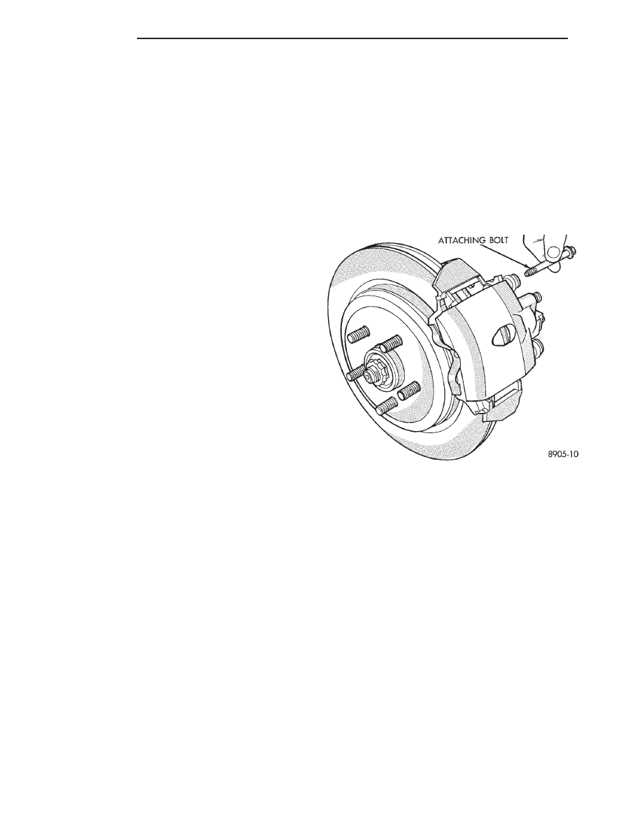
(3) Remove caliper attaching bolts (Fig. 2).
(4) Lift caliper away from adapter rails (Fig. 3).
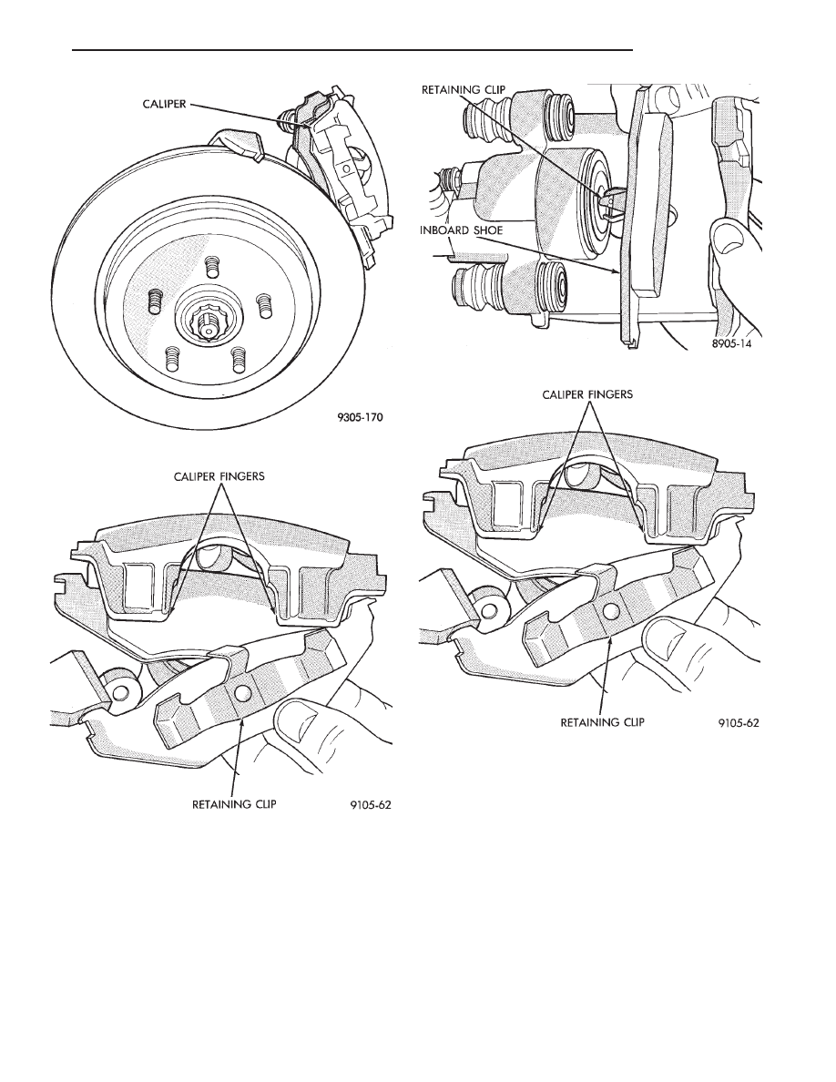
(5) Remove outboard shoe. By prying the shoe re-
taining clip over the raised area on the caliper. Then
slide the shoe down and off the caliper (Fig. 4).
(6) Pull inboard shoe away from piston, until the
retaining clip is free from the cavity in the piston. (Fig.
5).
CLEANING AND INSPECTION
Check for piston seal leaks (brake fluid in and
around boot area and inboard lining) and for any
ruptures of piston dust boot. If the boot is damaged, or
fluid leak is visible, disassemble caliper assembly and
install a new seal and boot (and piston if scored). Refer
to procedure titled Disc Brake Caliper Disassembly.
BRAKE SHOE INSTALLATION
(1) Retract piston.
If the originally removed brake shoe assem-
blies are to be replaced back on vehicle. Be sure
Fig. 2 Removing Caliper Attaching Bolts
5 - 46
BRAKES
Ä
each brake shoe assembly is returned to its origi-
nal position on the wheel of the vehicle from
which it was removed.
(2) Install inboard brake shoe by inserting shoe
retaining clip into piston cavity. Be sure brake shoe is
seated squarely on the face of the piston. (Fig. 5).
(3) Install outboard shoe by sliding retaining clip
over caliper fingers. Be sure the brake shoe is installed
on the caliper, so the retaining clip is past the raised
area on the caliper fingers (Fig. 6).
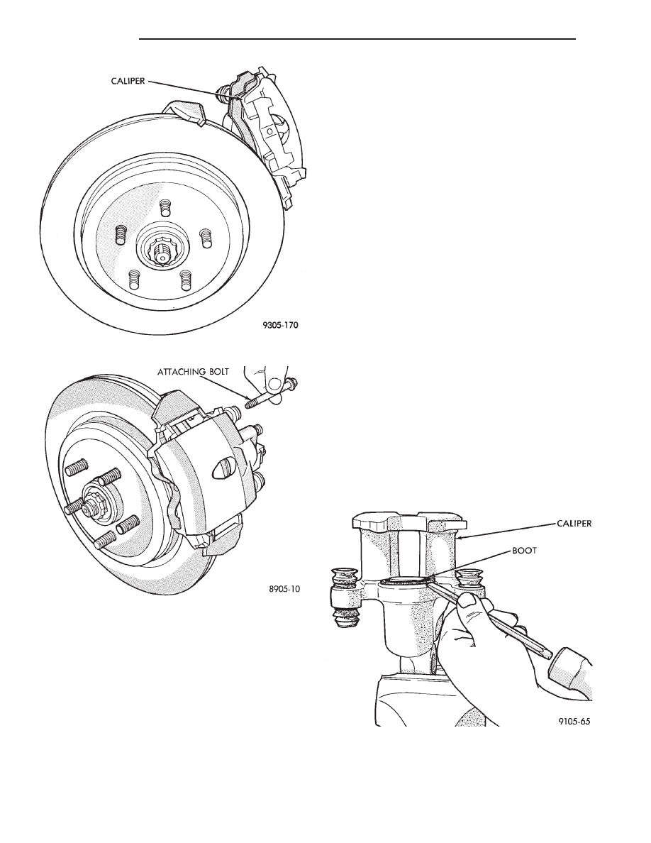
(4) Install lower end of caliper on to adapter. Make
sure the lower tabs on the brake shoes and the cast-
ing projections on the caliper are under the adapter
rail (Fig. 7).
(5) Rotate caliper down over rotor.
(6) Install caliper attaching bolts and tighten to 22
N
Im (193 in. lbs.) torque (Fig. 8).
(7) Install wheel and tire assembly. Tighten stud
nuts in proper sequence until all nuts are torqued to
half specification. This is important. Then repeat
sequence to full specification.
(8) Remove jackstands or lower hoist. Before mov-
ing vehicle be sure it has a firm pedal.
Fig. 5 Remove and Install Inboard Brake Shoe
Fig. 6 Installing Outboard Shoe
Fig. 3 Removing Caliper
Fig. 4 Removing Outboard Shoe
Ä
BRAKES
5 - 47
DISASSEMBLING REAR CALIPER ASSEMBLY
CLEANING AND INSPECTION
Check for piston fluid seal leaks (brake fluid in and
around boot area and inboard lining) and for any
ruptures of piston dust boot. If boot is damaged, or
fluid leak is visible, disassemble caliper assembly
and install a new seal and boot,(and piston if scored).
Refer to procedures titled Disc Brake Caliper Disas-
sembly.
Check the caliper dust boot and caliper pin bush-
ings to determine if they are in good condition. Re-
place if they are damaged, dry, or found to be brittle.
Refer to Cleaning And Inspection Of Brake Caliper.
(1) Remove caliper from braking disc (See Brake
Shoe Removal). Hang assembly on a wire hook away
from braking disc, so hydraulic fluid cannot get on
braking disc (See Fig. 4 in Brake Shoe Removal). Place
a small piece of wood between the piston and caliper
fingers.
(2) Carefully depress brake pedal to hydraulically
push piston out of bore. (Brake pedal will fall away
when piston has passed bore opening.) Then prop up
the brake pedal to any position below the first inch of
pedal travel, this will prevent loss of brake fluid from
the master cylinder.
(3) If both front caliper pistons are to be removed,
disconnect flexible brake line at frame bracket after
removing piston. Plug brake tube and remove piston
from opposite caliper. Using the same process as above
for the first piston removal.
WARNING: UNDER NO CONDITION SHOULD AIR
PRESSURE BE USED TO REMOVE PISTON FROM
CALIPER BORE. PERSONAL INJURY COULD RE-
SULT FROM SUCH A PRACTICE.
(4) Disconnect brake flexible hose from the caliper.
To disassemble, mount caliper assembly in a vise
equipped with protective jaws.
CAUTION: Excessive vise pressure will cause bore
distortion and binding of piston.
Support rear caliper assembly in a vise. Then remove
caliper to piston dust boot and discard (Fig. 1).
Using a plastic trim stick, work piston seal out of its
groove in caliper piston bore (Fig. 2). Discard old seal.
Do not use a screwdriver or other metal
Fig. 7 Installing Caliper
Fig. 8 Installing Attaching Bolts
Fig. 1 Removing Piston Dust Boot
5 - 48
BRAKES
Ä
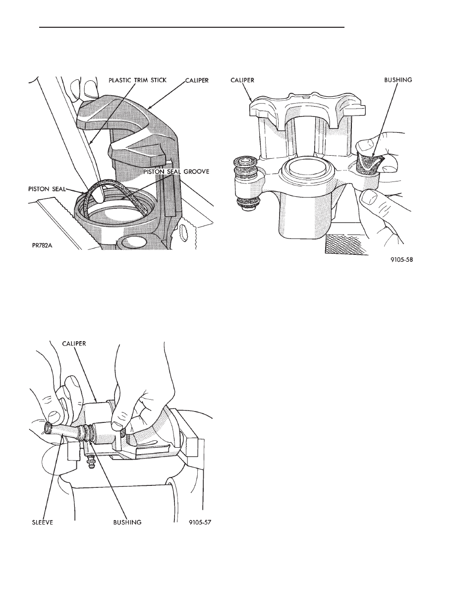
tool for this operation, because of the possibility
of scratching piston bore or burring edges of seal
groove.
The double pin caliper uses a sealed for life bushing
and sleeve assembly. If required this assembly can be
serviced using the following procedure.
(1) Using your fingers push on one end the inner
sleeve until it pops out of the bushing. Then grasp the
inner sleeve with your fingers and pull the inner sleeve
out from the inside of the bushing (Fig. 3).
(2) Using your fingers collapse one side of the bush-
ing. Then pull on the opposite side to remove the
bushing from the caliper assembly (Fig. 4).
CLEANING AND INSPECTION
Clean all parts using alcohol or a suitable solvent
and wipe dry. Clean out all drilled passages and bores
on the caliper assembly body. (Whenever a caliper
has been disassembled, a new boot and seal must
be installed at assembly).
Inspect the caliper assembly piston bore for scoring
or pitting. Bores that show light scratches or corrosion,
can usually have the scratches or corrosion removed
using crocus cloth.
Bores that have deep scratches or scoring should be
honed. Use Caliper Hone, Special Tool C-4095, or
equivalent providing the diameter of the bore is not
increased more than 0.0254 mm (0.001 inch) (Fig. 5).
If the bore does not clean up within this specification,
a new caliper housing should be installed. Install a new
piston if the old one is pitted or scored.
When using Caliper Honing Tool, Special Tool
C-4095, coat the stones and bore with brake fluid.
After honing the bore, carefully clean the seal
and boot grooves with a stiff non-metallic rotary
brush.
Use extreme care in cleaning the caliper after
honing. Remove all dirt and grit by flushing the
caliper with brake fluid; wipe dry with a clean,
lint free cloth and then clean a second time.
ASSEMBLING REAR DISC BRAKE CALIPER
Clamp caliper in vise (with protective caps on vise
jaws).
Fig. 2 Removing Piston Seal
Fig. 3 Removing Inner Sleeve From Bushing
Fig. 4 Removing Bushings From Caliper
Ä
BRAKES
5 - 49
Нет комментариевНе стесняйтесь поделиться с нами вашим ценным мнением.
Текст