Chrysler Le Baron, Dodge Dynasty, Plymouth Acclaim. Manual — part 224
CAUTION: Excessive vise pressure will cause bore
distortion and binding of piston.
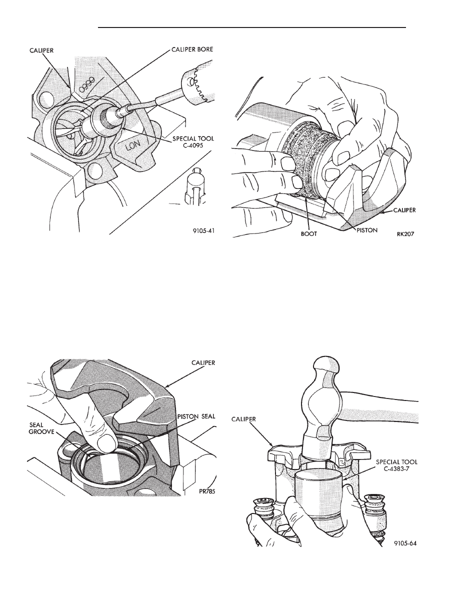
Dip new piston seal in clean brake fluid and install
in the groove of the caliper bore. Seal should be po-
sitioned at one area in groove and gently worked
around the groove (Fig. 6), using only your fingers
until properly seated.
NEVER USE AN OLD PISTON SEAL. (Be sure
that fingers are clean and seal is not twisted or
rolled) (Fig. 6).
Coat new piston boot with clean brake fluid leav-
ing a generous amount inside boot.
Position dust boot over piston after coating with
brake fluid.
Install piston into caliper bore pushing it past the
piston seal until it bottoms in the caliper bore (Fig.
7).
CAUTION: Force must be applied to the piston uni-
formly to avoid cocking and binding of the piston in
the bore of the caliper.
Position dust boot in counterbore of the caliper pis-
ton bore.
Using a hammer and Installer Piston Caliper Boot,
Special Tool C-4383-7 and Handle, Special Tool
C-4171, drive boot into counterbore of the caliper
(Fig. 8).
Fig. 5 Honing Piston Bore
Fig. 6 Installing New Piston Seal
Fig. 7 Pushing Piston into Bore
Fig. 8 Installing Boot in Caliper
5 - 50
BRAKES
Ä
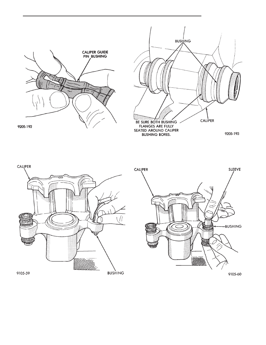
Use the following steps, to install the Guide Pin
Sleeve Bushings into the caliper assembly.
(1) Fold the bushing in half lengthwise at the solid
middle section of the bushing (Fig. 9).
(2) Using your fingers insert the folded bushing into
the caliper assembly (Fig. 10). Do not use a sharp
object to perform this step do to possible damage
to the bushing.
(3) Unfold the bushing using your fingers or a
wooden dowel until the bushing is fully seated into the
caliper assembly. Flanges should be seated evenly on
both sides of the bushing hole in the caliper assembly
(Fig. 11).
Install the Guide Pin Sleeve into the guide bushing
using the following procedure.
(1) Install the sleeve into one end of the bushing
until the seal area of the bushing is past the seal
groove in the sleeve (Fig. 12).
(2) Holding the convoluted end of the bushing with
one hand. Push the sleeve through the bushing (Fig.
13) until the one end of the bushing is fully seated
into the seal groove on the one end of the sleeve.
(3) Holding the sleeve in place work the other end
of the bushing over the end of the sleeve and into the
Fig. 11 Bushing Correctly Installed In Caliper
Fig. 12 Installing Caliper Sleeves
Fig. 9 Folded Caliper Guide Pin Bushing
Fig. 10 Installing Caliper Guide Pin Sleeve Bushings
Ä
BRAKES
5 - 51
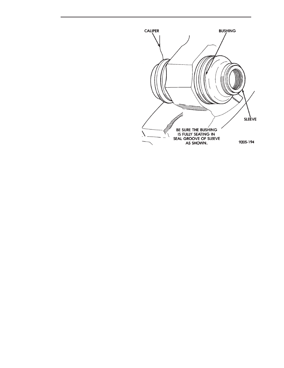
seal grove (Fig. 13). Be sure the other end of the
bushing did not come out of the seal grove in the sleeve.
(4) When the sleeve is seated properly into the
bushing. The sealed for life bushing can be held be-
tween your fingers and easily slid back and forth
without the bushing seal unseating from the sleeve.
Before installing caliper assembly on vehicle, inspect
braking disc. If any conditions as described in Check-
ing Braking Disc for Runout and Thickness are present
the braking disc, must be replaced or refaced. If the
braking disc does not require any servicing, install
caliper assembly.
Install brake hose onto caliper using banjo bolt.
Torque the brake hose to caliper assembly banjo bolt to
33 N
Im (24 ft. lbs.). New seal washers MUST al-
ways be used when installing brake hose to cali-
per.
Bleed the brake system (see Bleeding Brake System).
Pump the brake pedal several times to be sure that the
vehicle has a firm pedal, before the vehicle is moved or
driven.
Fig. 13 Installed Caliper Bushing Sleeve
5 - 52
BRAKES
Ä
BRAKE DISC (ROTOR)
INDEX
page
page
Braking Disc Removal
. . . . . . . . . . . . . . . . . . . . . 54
General Information
. . . . . . . . . . . . . . . . . . . . . . . 53
Inspection Diagnosis
. . . . . . . . . . . . . . . . . . . . . . 53
Installing Braking Disc
. . . . . . . . . . . . . . . . . . . . . 54
Refinishing Braking Disc
. . . . . . . . . . . . . . . . . . . 55
Service Procedures
. . . . . . . . . . . . . . . . . . . . . . . 53
GENERAL INFORMATION
Any servicing of the braking disc requires extreme
care to maintain the braking disc within service toler-
ances to ensure proper brake action.
CAUTION: If the braking disk (rotor) needs to be
replaced with a new part. The protective coating on
the braking surfaces of the rotor MUST BE REMOVED
with an appropriate solvent, to avoid contamination
of the brake shoe linings.
When replacing a rotor with a new part do NOT
reface the new rotor. Rotor already has the re-
quired micro finish when manufactured, only
remove the protective coating.
INSPECTION DIAGNOSIS
Before refinishing or refacing a braking disc, the disc
should be checked and inspected for the following
conditions:
Braking surface scoring, rust, impregnation of lining
material and worn ridges.
Excessive lateral rotor runout or wobble.
Thickness variation (Parallelism).
Dishing or distortion (Flatness).
If a vehicle has not been driven for a period of time.
The discs will rust in the area not covered by the brake
lining and cause noise and chatter when the brakes are
applied.
Excessive wear and scoring of the disc can cause
temporary improper lining contact if ridges are not
removed before installation of new brake shoe assem-
blies.
Some discoloration or wear of the disc surface is
normal and does not require resurfacing when linings
are replaced.
Excessive runout or wobble in a disc can increase
pedal travel due to piston knock back. This will in-
crease guide pin bushing wear due to tendency of
caliper to follow disc wobble.
Thickness variation in a disc can also result in pedal
pulsation, chatter and surge due to variation in brake
output. This can also be caused by excessive runout in
braking disc or hub.
Dishing or distortion can be caused by extreme heat
and abuse of the brakes.
SERVICE PROCEDURES
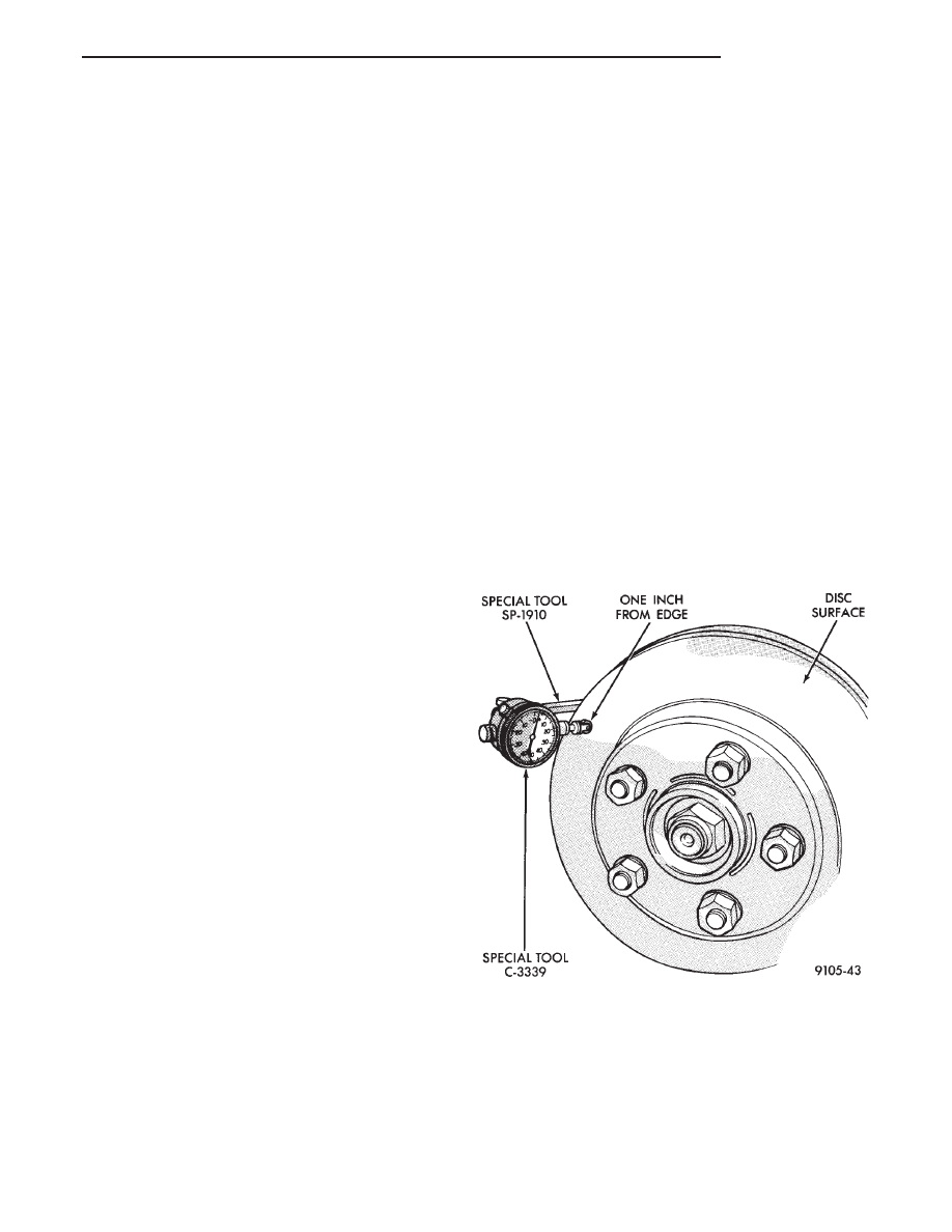
CHECKING BRAKING DISC FOR RUNOUT AND
THICKNESS
On vehicle, braking disc (rotor) runout is the com-
bination of the individual runout of the hub face and
the runout of the disc. (The hub and disc are separa-
ble). To measure runout on the vehicle, remove the
wheel and reinstall the lug nuts tightening the disc
to the hub. Mount Dial Indicator, Special Tool
C-3339 with Mounting Adaptor, Special Tool SP-1910
on steering arm. Dial indicator plunger should con-
tact disc (braking surface) approximately one inch
from edge of disc (See Fig. 1). Check lateral runout
(both sides of disc) runout should not exceed 0.13 mm
(0.005 inch).
If runout is in excess of the specification, check the
lateral runout of the hub face. Before removing disc
from hub, make a chalk mark across both the disc
and one wheel stud on the high side of runout. So
you’ll know exactly how the disc and hub was origi-
nally mounted (Fig. 2). Remove disc from hub.
Install Dial Indicator, Special Tool C-3339 and
Mounting Adaptor, Special Tool SP-1910 on steering
Fig. 1 Checking Braking Disc for Runout
Ä
BRAKES
5 - 53
Нет комментариевНе стесняйтесь поделиться с нами вашим ценным мнением.
Текст