Chrysler Le Baron, Dodge Dynasty, Plymouth Acclaim. Manual — part 596

ENGINE LUBRICATION SYSTEM
The lubrication system is a full flow filtration pres-
sure feed type. Oil from the oil pan is pumped by a
internal gear type oil pump directly coupled to the
crankshaft. Its pressure is regulated by a relief valve
located in the Chain Case Cover. The oil is pumped
through an oil filter and feeds a main oil galley.This
oil gallery feeds oil under pressure to the main and
rod bearings, camshaft bearings. Passages in the cyl-
inder block feed oil to the hydraulic lifters and
rocker shaft brackets which feeds the rocker arm piv-
ots (Fig. 1).
OIL PAN SERVICE
REMOVAL
(1) Disconnect negative battery cable, remove en-
gine oil dipstick.
(2) Raise vehicle. Drain engine oil.
(3) Remove oil pan screws and remove oil pan.
CLEANING AND INSPECTION
(1) Clean oil pan in solvent and wipe dry with a
clean cloth. Clean all gasket material from mounting
surfaces of pan and block.
(2) Inspect oil drain plug and plug hole for stripped
or damaged threads and repair as necessary. Install
a new drain plug gasket. Tighten to 27 N
Im (20 ft.
lb.).
(3) Inspect oil pan mounting flange for bends or
distortion. Straighten flange if necessary.
(4) Clean oil screen and pipe in clean solvent. In-
spect condition of screen.
INSTALLATION
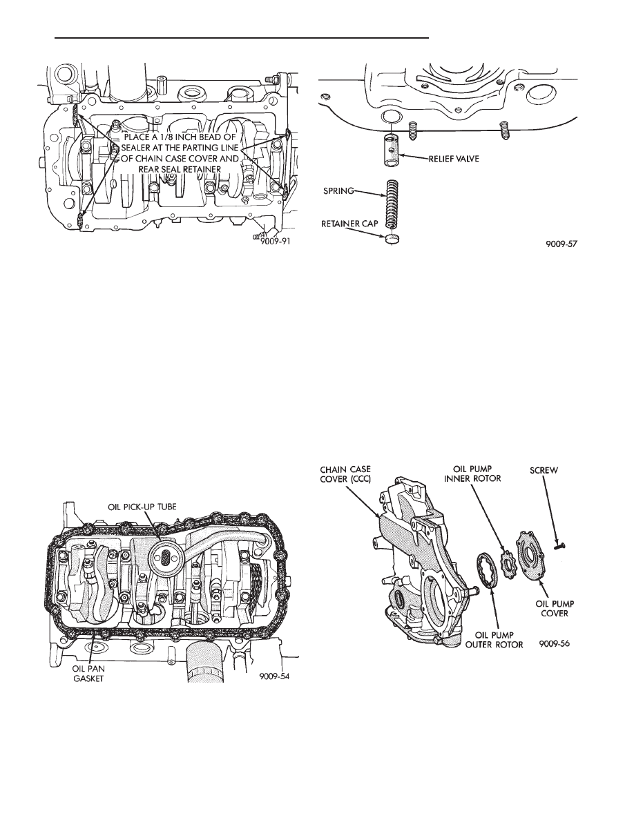
(1) Install oil pick-up tube into Chain Case Cover
tighten screw to 28 N
Im (250 in. lbs.) (Fig. 2).
(2) Apply a 1/8 inch bead of Mopar Silicone Rubber
Adhesive Sealant or equivalent, at the parting line of
the chain case cover and the rear seal retainer (Fig. 3).
(3) Use a new pan gasket (Fig. 4).
(4) Install pan and tighten screws to 23 N
Im (200 in.
lb.).
(5) Lower vehicle and install oil dipstick.
(6) Connect negative battery cable.
(7) Fill crankcase with oil to proper level.
Fig. 1 Engine Oiling System
Fig. 2 Oil Pump Pick-up Tube Service
9 - 122
3.3/3.8L ENGINE
Ä
OIL PUMP SERVICE
It is necessary to remove the oil pan, oil pickup
and chain case cover (CCC) to service the oil pump
rotors. The oil pump pressure relief valve can be ser-
viced by removing the oil pan and oil pickup tube.
Refer to Timing Chain Cover Removal and Installa-
tion of this section for procedures.
DISASSEMBLY
(1) To remove the relief valve, proceed as follows:
(a) Drill a 3.175mm (1/8 inch) hole into the relief
valve retainer cap and insert a self-threading sheet
metal screw into cap.
(b) Clamp screw into a vise and while supporting
chain case cover (CCC), remove cap by tapping
CCC using a soft hammer. Discard retainer cap
and remove spring and relief valve (Fig. 5).
(2) Remove oil pump cover screws, and lift off
cover.
(3) Remove pump rotors.
(4) Wash all parts in a suitable solvent and inspect
carefully for damage or wear (Fig. 6).
INSPECTION AND REPAIR
(1) Clean all parts thoroughly. Mating surface of
the chain case cover (CCC) should be smooth. Re-
place pump cover if scratched or grooved.
(2) Lay a straightedge across the pump cover sur-
face (Fig. 7). If a .076mm (.003 inch) feeler gauge can
be inserted between cover and straight edge, cover
should be replaced.
(3) Measure thickness and diameter of outer rotor.
If outer rotor thickness measures 7.64mm (0.0301
inch.) or less (Fig. 8), or if the diameter is 79.95mm
(3.148 inches.) or less, replace outer rotor.
(4) If inner rotor measures 7.64mm (.301 inch) or
less replace inner rotor (Fig. 9).
(5) Slide outer rotor into CCC, press to one side
with fingers and measure clearance between rotor
and CCC (Fig. 10). If measurement is .39mm (.015
inch) or more, replace CCC only if outer rotor is in
specification.
(6) Install inner rotor into CCC. If clearance be-
tween inner and outer rotors (Fig. 11) is .203mm
(.008 inch) or more, replace both rotors.
Fig. 3 Oil Pan Sealing
Fig. 4 Oil Pan Gasket Installation
Fig. 5 Oil Pressure Relief Valve
Fig. 6 Oil Pump
Ä
3.3/3.8L ENGINE
9 - 123

(7) Place a straightedge across the face of the CCC,
between bolt holes. If a feeler gauge of .102mm (.004
inch) or more can be inserted between rotors and the
straightedge, replace pump assembly (Fig. 12). ONLY
if rotors are in specs.
(8) Inspect oil pressure relief valve plunger for scor-
ing and free operation in its bore. Small marks may be
removed with 400-grit wet or dry sandpaper.
(9) The relief valve spring has a free length of
approximately 49.5mm (1.95 inches) it should test
between 19.5 and 20.5 pounds when compressed to
34mm (1-11/32 inches). Replace spring that fails to
meet specifications (Fig. 5).
(10) If oil pressure is low and pump is within speci-
fications, inspect for worn engine bearings or other
reasons for oil pressure loss.
OIL PUMP ASSEMBLY AND INSTALLATION
(1) Assemble pump, using new parts as required.
Install the inner rotor with chamfer facing the
cast iron oil pump cover.
(2) Tighten cover screws to 12 N
Im (105 in. lbs.).
(3) Prime oil pump before installation by filling ro-
tor cavity with engine oil.
(4) Install chain case cover slowly refer to Timing
Chain Cover Installation of this section.
Fig. 9 Measuring Inner Rotor Thickness
Fig. 10 Measuring Outer Rotor Clearance in
Housing
Fig. 11 Measuring Clearance Between Rotors
Fig. 7 Checking Oil Pump Cover Flatness
Fig. 8 Measuring Outer Rotor Thickness
9 - 124
3.3/3.8L ENGINE
Ä
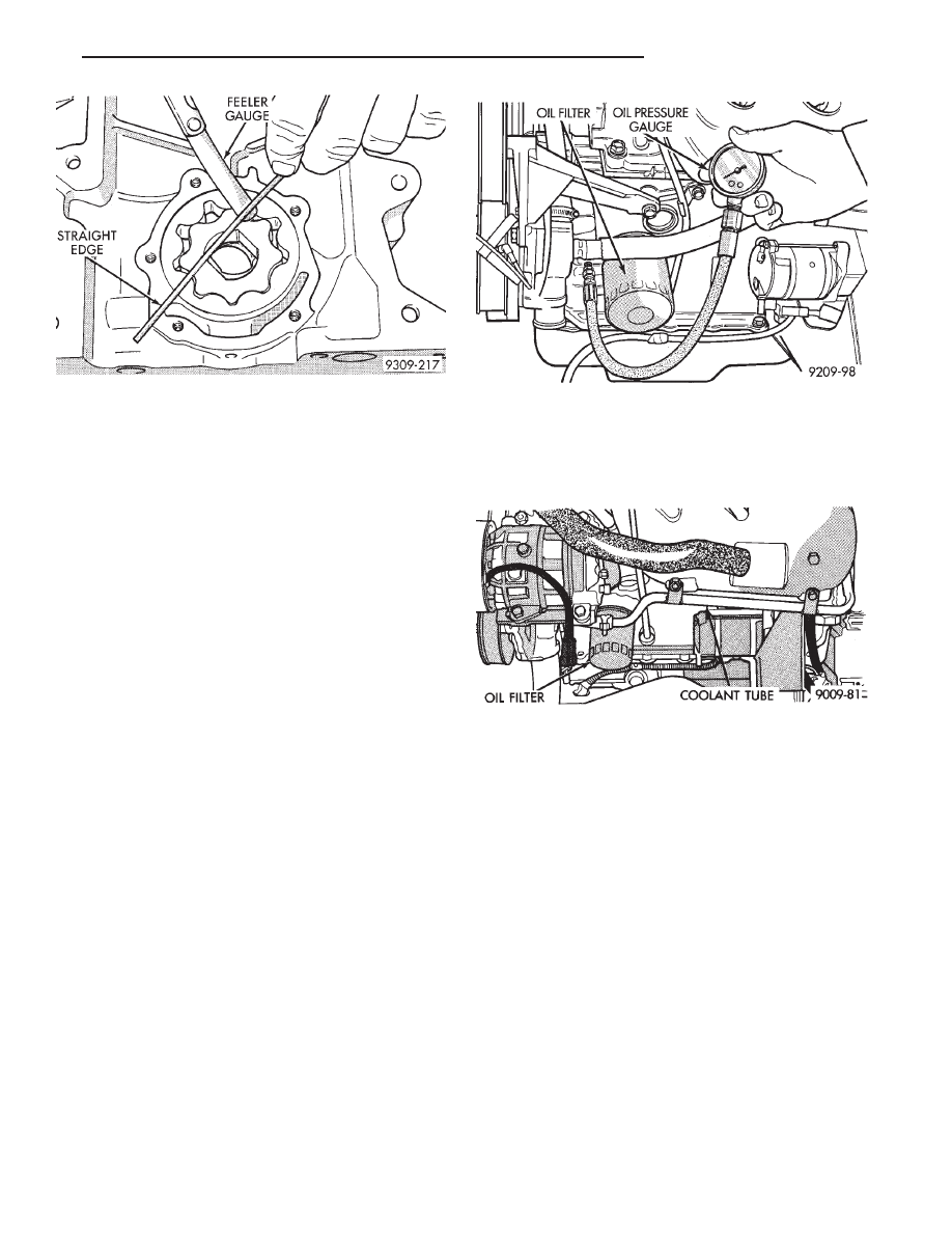
CHECKING ENGINE OIL PRESSURE
Check oil pressure using gauge at oil pressure
switch location. Oil pressure should be 34.47 kPa ( 5
psi.) at idle or 205 to 551 kPa (30 to 80 psi.) at 3000
RPM.
(1) Remove pressure sending unit and install oil
pressure gauge (Fig. 13).
CAUTION: If oil pressure is 0 at idle, Do Not Run
engine at 3000 RPM.
(2) Warm engine at high idle until thermostat
opens.
OIL FILTER
CAUTION: When servicing the oil filter (Fig. 16)
avoid deforming the filter can by installing the re-
move/install tool band strap against the can-to-base
lockseam. The lockseam joining the can to the base
is reinforced by the base plate.
(1) Using Tool C-4065, unscrew filter from base
and discard (Fig. 14).
(2) Wipe base clean, then inspect gasket contact
surface.
(3) Lubricate gasket of new filter with clean en-
gine oil.
(4) Install and tighten filter to 20 N
Im (15 ft. lbs.)
torque after gasket contacts base. Use filter wrench
if necessary.
(5) Start engine and check for leaks.
Fig. 12 Measuring Clearance Over Rotors
Fig. 13 Checking Oil Pump Pressure
Fig. 14 Oil Filter
Ä
3.3/3.8L ENGINE
9 - 125
Нет комментариевНе стесняйтесь поделиться с нами вашим ценным мнением.
Текст