Chrysler Le Baron, Dodge Dynasty, Plymouth Acclaim. Manual — part 77

Fig.
1
Alignment
Camber/T
oe
2 - 6
SUSPENSION AND DRIVESHAFTS
Ä

WHEEL ALIGNMENT SERVICE PROCEDURE
CAMBER AA, AJ BODIES
(1) Prepare vehicle as described in the Pre-Align-
ment procedure.
(2) Loosen cam and knuckle bolts (each side) (Fig.
2).
(3) Rotate cam bolt (Fig. 2) to move top of wheel in
or out to specified camber.
(4) Tighten the cam bolts and nuts to 100 N
Im (75
ft. lbs.) plus 1/4 turn beyond specified torque.
CAMBER AC, AG, AP, AY BODIES
(1) Prepare vehicle as described in the Pre-Align-
ment procedure.
(2) Position vehicle on alignment equipment and
read camber as instructed by equipment manufactur-
er’s procedure.
(3) Using extensions and appropriate tools. Re-
move the strut assembly to steering knuckle attach-
ing bolts from vehicle (Fig. 2). Replace the original
attaching bolts with the bolts provided in the align-
ment, Cam And Bolt Service Package.
(4) Rotate the alignment adjusting cam bolt, (Fig.
2) to obtain the specified camber setting for the ve-
hicle. See the Specifications Section at the end of this
group for the camber setting for the vehicle being
serviced.
(5) Using the appropriate extensions and tools.
Carefully reach around the tire and tighten the
knuckle bolts enough to hold the camber setting.
Finish by tightening the bolts to 100 N
Im (75 ft.lbs.)
plus 1/4 turn beyond specified torque.
TOE
(1) Prepare vehicle as described in the Pre-Align-
ment procedure.
(2) Center steering wheel and hold with steering
wheel clamp.
(3) Loosen tie rod locknuts. Rotate rods to align toe
to specifications (Fig. 3).
CAUTION: Do not twist tie rod to steering gear rub-
ber boots during adjustment.
(4) Tighten tie rod locknuts to 75 N
Im (55 ft.lbs.)
torque.
(5) Adjust steering gear to tie rod boots at tie rod.
(6) Remove steering wheel clamp.
STRUT DAMPER ASSEMBLY
REMOVAL
(1) Loosen wheel nuts.
(2) Raise vehicle, see Hoisting in Lubrication and
Maintenance, Group 0.
(3) Remove wheel and tire assembly.
Where service procedure includes assembly of
original
strut
(shock
absorber)
to
original
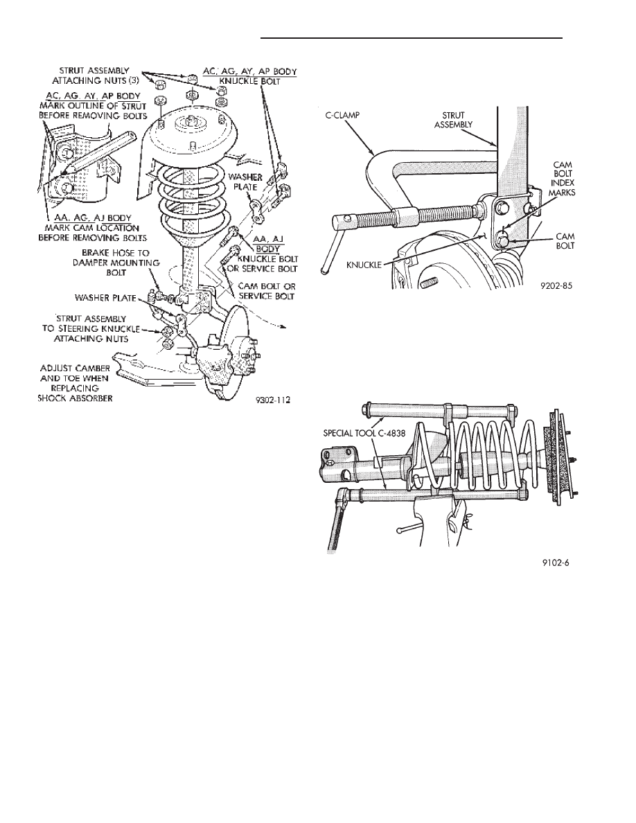
knuckle. Mark cam adjusting bolt (Fig. 4), on
AA, and AJ bodies only. Mark outline of strut
on knuckle as shown in (Fig. 1). on AC, AG, AP
and AY bodies.
(4) Remove cam bolt, knuckle bolt(s), washer
plate(s) and brake hose to damper bracket retaining
screw (Fig. 4).
(5) Remove strut damper to fender shield mount-
ing nut washer assemblies.
Fig. 2 Alignment Adjustment Locations
Fig. 3 Front Wheel Toe Adjustment
Ä
SUSPENSION AND DRIVESHAFTS
2 - 7
INSPECTION
Inspect for evidence of fluid running from the up-
per end of the reservoir. (Actual leakage will be a
stream of fluid running down the side and dripping
off lower end of unit). A slight amount of seepage be-
tween the strut rod and strut shaft seal is not un-
usual and does not affect performance of the strut
assembly.
INSTALLATION
(1) Install unit into fender reinforcement and in-
stall retaining nuts and washer assemblies (Fig. 1).
Tighten the 3 nuts to 27 N
Im (20 ft. lbs.) torque.
(2) Position steering knuckle neck into strut as-
sembly. Position washer plate and install cam and
knuckle bolts (Fig. 4).
(3) Attach brake hose retainer to damper, tighten
the screw to 13 N
Im (10 ft. lbs.) torque (Fig. 4).
(4) Index strut to original outline on the knuckle
neck, or align mark on cam bolt with the mark that
was put on the strut to steering knuckle bracket
(Fig. 4).
(5) Place a 4 inch (or larger) C clamp on the strut
and knuckle as shown in (Fig. 5). Tighten the clamp
just enough to eliminate any looseness between the
knuckle and the strut. Check alignment of the index
marks and tighten the bolts to 100 N
Im (75 ft. lbs.)
plus 1/4 turn beyond specified torque. Remove the
(C) clamp.
(6) Install wheel and tire assembly. Tighten the
wheel nuts to 129 N
Im (95 ft. lbs.) torque.
DISASSEMBLY (STRUT DAMPER)
(1) Compress front coil spring with Spring Com-
pressor, Special Tool C-4838 (Fig. 6).
(2) Hold end of strut shaft from rotating with
wrench, while loosening strut shaft nut. Remove nut
from shaft (Fig. 7).
(3) Remove the upper strut mount from the strut
assembly.
(4) Remove coil spring from the strut assembly.
Mark spring for installation back on the same
side of the vehicle (Fig. 11).
CAUTION: see Suspension Coil Springs before re-
leasing coil from Tool C-4838.
(5) Inspect strut damper, mount assembly (Fig. 8)
for:
Fig. 4 Strut Damper Removal
Fig. 5 Strut Damper Installation
Fig. 6 Compressing Coil Spring
2 - 8
SUSPENSION AND DRIVESHAFTS
Ä

(a) Severe deterioration of rubber isolator; re-
tainers for cracks and distortion and bond failure of
retainers and rubber isolators.
(b) Bearings for binding.
(c) Shock Absorber for flat spots over full stroke
also see, Shock Absorbers, (strut damper).
ASSEMBLE (STRUT DAMPER)
(1) Mount the strut assembly in a vertical position.
(2) Place the compressed spring onto the strut as-
sembly, so the end of the coil is seated in the seat re-
cess in lower spring mount (Fig. 9).
(3) Install the dust shield, isolator (if so equipped)
jounce bumper, spacer (as required), and spring seat
onto the top of the strut shaft (Fig. 8).
(4) Position top spring seat alignment tab correctly
with respect to bottom bracket (Fig. 9).
(5) Install the rebound retainer and shaft nut (Fig.
8).
(6) Tighten the strut shaft nut using, Strut Rod
Socket And Holder, Special Tool L-4558. Torque strut
shaft nut to 75 N
Im (55 ft. lbs.) plus 1/4 turn (Fig. 10).
WARNING: THIS STEP MUST BE DONE BEFORE
SPRING COMPRESSOR, SPECIAL TOOL C-4838 IS
RELEASED FROM THE COIL SPRING.
(7) Verify coil spring is aligned correctly with respect
to bottom bracket (Fig. 9).
(8) Release Spring Compressor Tool C-4838.
SUSPENSION COIL SPRINGS
Springs are rated separately for each side of vehicle
depending on optional equipment and type of service.
During service procedures where both springs are
removed, mark springs (Chalk, Tape, etc.) (Fig. 11) to
ensure installation in original position. If the coils
springs require replacement. Be sure that the
springs needing replacement, are replaced with
springs meeting the correct load rating for the
vehicle and its specific options.
During service procedures requiring the re-
moval or installation of a coil spring with Spring
Fig. 7 Loosening Strut Assembly Shaft Nut
Fig. 8 Mount Assembly
Fig. 9 Spring Seat Alignment Notch Position to
Bracket
Fig. 10 Tighten Strut Rod Nut with Tool
Ä
SUSPENSION AND DRIVESHAFTS
2 - 9
Нет комментариевНе стесняйтесь поделиться с нами вашим ценным мнением.
Текст