Chrysler Le Baron, Dodge Dynasty, Plymouth Acclaim. Manual — part 124
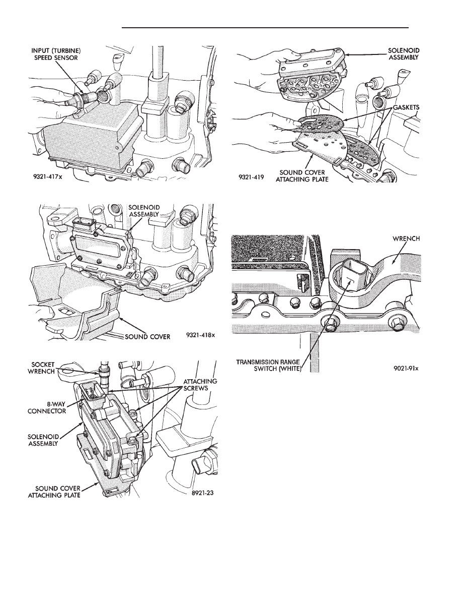
TRANSMISSION RANGE SWITCH
The transmission range switch is the white switch
located on the front of the transaxle, just above the
transaxle oil pan.
CAUTION: Switch seal washer must be seated prop-
erly before tightening switch. Failure to do so may
result in leakage of transmission fluid (Fig. 6).
PARK/NEUTRAL POSITION SWITCH
The Park/Neutral Position Switch is the black
switch located to the right of the transmission range
switch.
CAUTION: Switch seal washer must be seated prop-
erly before tightening switch. Failure to do so may
result in leakage of transmission fluid (Fig. 7).
SPEED SENSOR-INPUT
CAUTION: When disconnecting speed sensor con-
nector, be sure that the weather seal does not fall
off or remain in old sensor.
The input speed sensor is located to the right of the
manual shift lever.
Fig. 2 Input Speed Sensor Removed
Fig. 3 Sound Cover
Fig. 4 Attaching Screws
Fig. 5 Solenoid Assembly
Fig. 6 Transmission Range Switch
21 - 102
TRANSAXLE
Ä
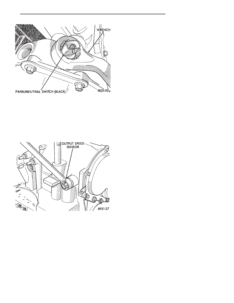
SPEED SENSOR-OUTPUT
CAUTION: When disconnecting speed sensor con-
nector, be sure that the weather seal does not fall
off or remain in old sensor.
The output speed sensor is located to the left of the
manual shift lever (Fig. 8).
TRANSMISSION CONTROL MODULE
When replacing a transmission control module, do
not interchange transmission control modules with
previous year transmission control modules. If a
same year transmission control module is being used
from a different vehicle, the following procedures
must be performed before operating the transaxle:
• Quick Learn Procedure
• Torque Converter Clutch Break-in Procedure
• Electronic Pinion Procedure
The transmission control module is located on the
passenger side of the engine compartment. It is held
in place by four mounting screws.
If the transmission control module has been
replaced, the following procedures must be per-
formed:
• ‘‘Quick Learn Procedure’’. This procedure will al-
low the transmission control module to learn the
characteristics of the vehicle.
• ‘‘Electronic Pinion Procedure’’. This procedure will
reprogram settings within the transmission control
module to compensate for different tire sizes and fi-
nal drive ratios.
• ‘‘Converter Clutch Break-In Procedure’’ This proce-
dure will reset the torque converter clutch status.
REMOVAL AND INSTALLATION
(1) Loosen 60 way retaining screw, located in the
center of the 60 way connector. Then disconnect the
60 way connector on transmission control module.
(2) Remove transmission control module mounting
screws and lift module from vehicle.
To install, reverse removal procedure.
TRANSAXLE QUICK LEARN PROCEDURE
The quick learn procedure requires the use of the
DRB II scan tool and the 1993 DRB II scan tool car-
tridge.
This program allows the electronic transaxle sys-
tem to recelebrate itself to provide the best possible
transaxle
operation.
The
quick
learn
procedure
should be performed if any of the following proce-
dures are performed:
• Transaxle Assembly Replacement
• Transmission Control Module Replacement
• Solenoid Pack Replacement
• Clutch Plate and/or Seal Replacement
• Valve Body Replacement or Recondition
(1) Plug the DRB II scan tool into the blue CCD
Buss connector. The connector is located under the
instrument panel on the drivers side of the vehicle.
(2) Insert the 1993 DRB II scan tool cartridge into
the DRB II scan tool.
(3) The red and green lights on the DRB II scan
tool will light up and then begin flashing. Wait until
the lights stop flashing before continuing with this
procedure.
(4) Press the number 4 key on the DRB II scan
tool key pad. Item number 4 will not appear on the
DRB II scan tool screen unless you scroll down. It is
not necessary to scroll down to be able to choose item
4.
(5) Press the number 2 on the DRB II scan tool
key pad (Transmission).
(6) Press the number 1 on the DRB II scan tool
key pad. Wait for the DRB II scan tool to perform the
following three tests before continuing (These tests
are done automatically by the DRB II scan tool).
• Buss Test
• Initialize
• Controller Part Number
Fig. 7 Park/Neutral Position Switch
Fig. 8 Output Speed Sensor
Ä
TRANSAXLE
21 - 103
(7) Press the number 5 on the DRB II scan tool
key pad (Adjustments).
(8) Press the number 3 on the DRB II scan tool
key pad (Quick Learn). Then follow the instructions
on the DRB II scan tool screen.
PINION FACTOR PROCEDURE
The vehicle speed readings for the speedometer are
taken from the output speed sensor. Because of dif-
ferent tire sizes and final drive ratios, the transmis-
sion control module must be calibrated to reflect the
different combinations of equipment. A procedure has
been developed called Pinion Factor. It allows the
technician to set the transmission control module ini-
tial setting so that the speedometer readings will be
correct.
Failure to perform this procedure will cause a ‘‘No
Speedometer Operation’’ condition.
This procedure must be performed if the transmis-
sion control module has been replaced.
To properly read or reset the Pinion Factor, it is
necessary to use a DRB II scan tool. Perform the fol-
lowing steps with the DRB II scan tool to read or re-
set the Pinion Factor:
(1) Plug the DRB II scan tool into the blue CCD
Bus connector. The connector is located under the in-
strument panel on the drivers side of the vehicle.
(2) Insert the 1993 DRB II scan tool cartridge into
the DRB II scan tool.
(3) The red and green lights on the DRB II scan
tool will light up and then begin flashing. Wait until
the lights stop flashing before continuing with this
procedure.
(4) Press the number 4 key (Select System) on the
DRB II scan tool key pad. Item number 4 will not ap-
pear on the DRB II scan tool screen unless you scroll
down. It is not necessary to scroll down to be able to
choose item 4.
(5) Press the number 2 on the DRB II scan tool
key pad (Transmission).
(6) Press the number 1 on the DRB II scan tool
key pad. Wait for the DRB II scan tool to perform the
following three tests before continuing (These tests
are done automatically by the DRB II scan tool).
• Bus Test
• Initialize
• Transmission Control Module Part Number
(7) Press the number 5 on the DRB II scan tool
key pad (Adjustments).
(8) Press the number 2 on the DRB II scan tool
key pad (Pinion Factor). Then follow the instructions
on the DRB II scan tool screen.
TORQUE CONVERTER CLUTCH BREAK-IN
PROCEDURE
A torque converter clutch break-in program is be-
ing used on all models with a 41TE. This program
will properly condition the torque converter clutch.
This will eliminate shudder during partial torque
converter clutch operation on a new torque converter.
If the torque converter is replaced, the new clutch
within the torque converter will require break-in.
The current break-in status stored in the transmis-
sion control module will have to be reset to the start
of break-in with the DRB II scan tool.
If a new transmission control module is put on the
vehicle, the status will be at the start of break-in.
This status is acceptable regardless of the mileage on
the torque converter. No modification of the break-in
status is required.
To properly service these vehicles, it is necessary to
use a DRB II scan tool to read or reset the break-in
status. Perform the following steps with the DRB II
scan tool to reset the break-in status:
(1) Plug the DRB II scan tool into the blue CCD
Bus connector. The connector is located under the in-
strument panel on the drivers side of the vehicle.
(2) Insert the 1993 DRB II scan tool cartridge into
the DRB II scan tool.
(3) The red and green lights on the DRB II scan
tool will light up and then begin flashing. Wait until
the lights stop flashing before continuing with this
procedure.
(4) Press the number 4 key (Select System) on the
DRB II scan tool key pad. Item number 4 will not ap-
pear on the DRB II scan tool screen unless you scroll
down. It is not necessary to scroll down to be able to
choose item 4.
(5) Press the number 2 on the DRB II scan tool
key pad (Transmission).
(6) Press the number 1 on the DRB II scan tool
key pad. Wait for the DRB II scan tool to perform the
following three tests before continuing (These tests
are done automatically by the DRB II scan tool).
• Bus Test
• Initialize
• Transmission Control Module Part Number
(7) Press the number 5 on the DRB II scan tool
key pad (Adjustments).
(8) Press the number 1 on the DRB II scan tool
key pad (Reset LU Clutch). The DRB II scan tool will
display one of three screens.
(a) LU Clutch Break-in Status: Start
(b) LU Clutch Break-in Status: In-progress
Press ENTER to Reset Break-in status
(c) LU Clutch Break-in Status: Complete Press
ENTER to Reset Break-in status
If screen (a) appears, the transmission control mod-
ule is at the beginning of its break-in program. No
further action is required.
If screen (b) appears, the transmission control mod-
ule is in the middle of a its break-in program. Press
the enter key on the DRB II scan tool key pad to re-
turn the status to the start of break-in.
21 - 104
TRANSAXLE
Ä
If screen (c) appears, the transmission control mod-
ule has completed its break-in status program. Press
the enter key on the DRB II scan tool key pad to return
the status to the start of break-in.
(9) After pressing the enter key a second time in step
8 a screen will appear that says ‘‘RESET LU CLUTCH
ARE YOU SURE ?’’. Press the enter key on the DRB II
scan tool key pad. The DRB II scan tool will then carry
out the reset command.
(10) After the DRB II scan tool completes the reset
command, a screen will appear saying ‘‘LU Clutch
Break-in Status has been RESET to Start’’. This screen
will indicate that the reset procedure has been success-
fully completed.
(11) Disconnect the DRB II scan tool from the blue
CCD Bus connector.
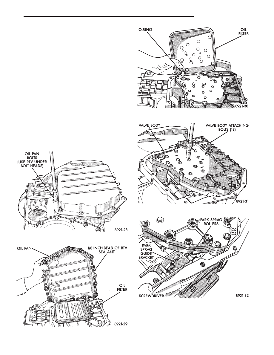
TRANSAXLE RECONDITION
Tag all clutch pack assemblies, as they are
removed, for reassembly identification.
CAUTION: Do not intermix clutch discs or plates as
the unit might then fail.
Fig. 1 Oil Pan Bolts
Fig. 2 Oil Pan
Fig. 3 Oil Filter
Fig. 4 Valve Body Attaching Bolts
Fig. 5 Push Park Rod Rollers from Guide Bracket
Ä
TRANSAXLE
21 - 105
Нет комментариевНе стесняйтесь поделиться с нами вашим ценным мнением.
Текст