Chrysler Le Baron, Dodge Dynasty, Plymouth Acclaim. Manual — part 184
(3) Remove cushion from vehicle.
REAR SEAT CUSHION INSTALLATION
Reverse the preceding operation.
REAR SEAT BACK REMOVAL
(1) Remove rear seat cushion assembly.
(2) Remove bolts holding seat back to rear floor
kick-up.
(3) Lift seat back upward to disengage upper hooks
from shelf support panel.
(4) Separate seat back from vehicle.
REAR SEAT BACK INSTALLATION
Reverse the preceding operation.
BODY MOULDINGS
STICK-ON BODY SIDE MOULDING REMOVAL
AND INSTALLATION
(1) Warm the effected stick-on moulding and body
metal to approximately 38°C (100°F) using a suitable
heat lamp or heat gun.
(2) Pull stick-on moulding from painted surface.
(3) Remove adhesive tape residue from painted
surface of vehicle.
(4) If moulding is to be reused, Remove tape resi-
due from moulding. Clean back of moulding with Mo-
par,
Super
Kleen
solvent
or
equivalent.
Wipe
moulding dry with lint free cloth. Apply new body
side moulding (two sided adhesive) tape to back of
moulding.
(5) Clean body surface with Mopar, Super Kleen
solvent or equivalent. Wipe surface dry with lint free
cloth.
(6) Apply a length of masking tape on the body,
parallel to the top edge of the moulding to use as a
guide, if necessary.
(7) Remove protective cover from tape on back of
moulding. Apply moulding to body below the mask-
ing tape guide.
(8) Remove masking tape guide and heat body and
moulding, see step one. Firmly press moulding to
body surface to assure adhesion.
FRONT WHEEL OPENING MOULDING
REMOVAL
(1) Remove screws holding wheel opening mould-
ing to front fender.
(2) Separate moulding from fender.
FRONT WHEEL OPENING MOULDING
INSTALLATION
(1) Position moulding in wheel opening and start
top center screw of wheel opening moulding.
(2) Install screws around wheel opening.
REAR WHEEL OPENING MOULDING REMOVAL
(1) Remove screws holding wheel opening mould-
ing to quarter panel.
(2) Separate wheel opening moulding from quarter
panel.
REAR WHEEL OPENING MOULDING
INSTALLATION
(1) Position moulding in wheel opening and start
top center screw of wheel opening moulding.
(2) Install screws around wheel opening.
VINYL ROOF BONNET
REMOVAL (FIG. 30)
(1) Remove quarter panel trim covers.
(2) Remove head lining.
(3) Remove nuts holding transverse roof moulding
to roof panel and separate moulding from vehicle.
(4) Remove nuts holding vinyl top bonnet to roof.
(5) Remove rear deck filler panel.
(6) Remove screws holding rear window opening
lower valance to body.
(7) Disengage clips holding vinyl top bonnet to
quarter panel.
(8) Pull vinyl top bonnet away from top panel to
separate bonnet from anti-flutter sealer holding bon-
net to roof.
INSTALLATION
(1) Clean anti-flutter sealer from roof surface and
inside of vinyl roof bonnet.
(2) Apply a 20 mm (0.75 in.) bead of anti-flutter
sealer across the roof panel at the mid point between
the front of the bonnet and rear of roof.
(3) Apply a 20 mm (0.75 in.) by 150 mm (6 in.)
bead of anti-flutter sealer down each roof side panel
at mid point between the door opening and rear of
roof.
(4) Place the bonnet into position on the roof panel
and align to proper fit.
(5) Reverse the removal operation.
REAR DECK FILLER PANEL
REMOVAL (FIG. 31)
(1) Raise truck lid to full up position.
(2) Remove screws holding rear deck filler panel to
body in the front trunk opening gutter.
(3) Close trunk lid, do not latch.
(4) Lift filler panel upward and separate from ve-
hicle.
INSTALLATION
Reverse the preceding operation.
23 - 146
AY-BODY
Ä

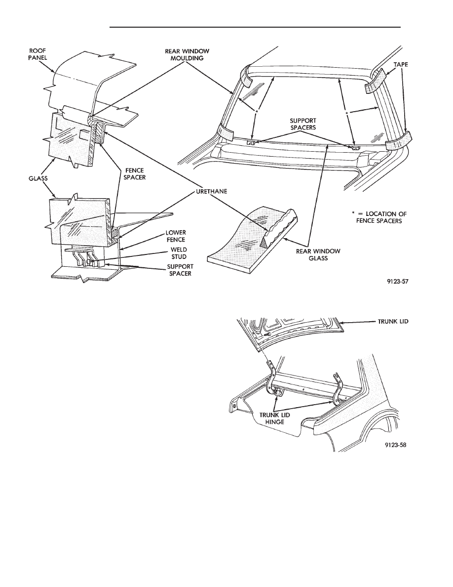
REAR WINDOW GLASS
REMOVAL (FIG. 32)
(1) Remove rear deck filler panel.
(2) Remove interior trim as necessary to gain ac-
cess to rear window defogger wire connector and
ground screw, if equipped.
(3) Remove vinyl roof bonnet, if equipped.
WARNING: WEAR EYE AND HAND PROTECTION
WHEN HANDLING SAFETY GLASS. PERSONAL IN-
JURY CAN RESULT.
CAUTION: Do not damage body or trim finish when
cutting out glass or applying fence primer.
(4) Cut the urethane around the perimeter of the
back window glass. Refer to Windshield section of
this group for proper procedures.
(5) Separate the rear window from the vehicle.
INSTALLATION
(1) Prepare the work area, window fence, and glass
the same way as described in the Windshield section
of this group.
(2) Place fence spacers at the locations shown (Fig.
32).
(3) Apply a 10 mm (0.4 in.) bead of urethane
around the perimeter of the glass.
(4) Install the glass in the same manner described
in the Windshield section of this group.
(5) Install roof bonnet.
(6) Connect rear window defogger wiring. Install
interior trim and rear deck filler panel.
(7) After urethane has cured, water test rear win-
dow to verify repair. Verify rear window defogger op-
eration, see Group 8N, Rear Window Defogger.
TRUNK LID
REMOVAL (FIG. 33)
(1) Raise trunk lid to full up position.
(2) Disconnect the trunk lamp wire connector.
(3) Mark all bolt and hinge attachment locations
with a grease pencil or other suitable device to pro-
vide reference marks for installation. When install-
ing trunk lid, align all marks and secure bolts. The
trunk lid should be aligned to 4 mm (0.160 in.) gap
to the quarter panels and flush across the top sur-
faces along quarter panels.
(4) Remove the top trunk lid to hinge attaching
bolts and loosen the bottom bolts until they can be
removed by hand.
(5) With assistance of a helper at the opposite side
of the vehicle to support the trunk lid, remove the
bottom trunk lid to hinge attaching bolts. Separate
the trunk lid from the vehicle.
INSTALLATION
Reverse the preceding operation.
TRUNK LID HINGE
REMOVAL
(1) Remove rear deck filler panel.
(2) Disconnect trunk lid lift torsion bars from
hinges.
(3) Mark all attaching bolt, nut, and component lo-
cations with a suitable marking device. Use marks
as a reference when installing hinge.
(4) Remove bolts holding trunk lid to hinge.
(5) Remove nuts and bolts holding hinge to closure
panel below rear window glass.
(6) Separate hinge from vehicle.
Fig. 30 Vinyl Roof Bonnet—Typical
Fig. 31 Rear Deck Filler Panel—Typical
Ä
AY-BODY
23 - 147
INSTALLATION
Reverse the preceding operation.
TRUNK LID TORSION BAR
REMOVAL
(1) Raise and support trunk lid in the full up posi-
tion.
(2) Remove trunk lining as necessary to gain ac-
cess to torsion bars.
(3) Disengage adjusting end torsion bar from the
slot in the tension adjustment bracket.
(4) Pivot torsion bar out of lift arm swivel.
(5) Disconnect torsion bar from hinge.
INSTALLATION
Reverse the preceding operation.
Fig. 32 Rear Window Glass—Typical
Fig. 33 Trunk Lid
23 - 148
AY-BODY
Ä
HEATING AND AIR CONDITIONING
CONTENTS
page
page
AUTOMATIC TEMPERATURE CONTROL
(ATC)
. . . . . . . . . . . . . . . . . . . . . . . . . . . . . . 66
COMPONENT SERVICE PROCEDURES
. . . . . . 47
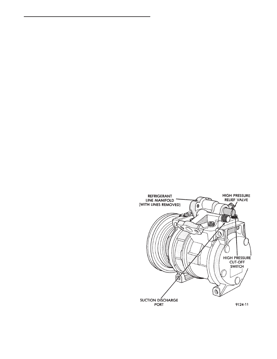
FIXED DISPLACEMENT COMPRESSOR—
MODEL 10PA17
. . . . . . . . . . . . . . . . . . . . . . 24
FIXED DISPLACEMENT COMPRESSOR—
MODEL SD709P
. . . . . . . . . . . . . . . . . . . . . . 38
FIXED DISPLACEMENT COMPRESSOR—
MODEL TR105
. . . . . . . . . . . . . . . . . . . . . . . 32
GENERAL INFORMATION . . . . . . . . . . . . . . . . . . 1
HEATER AND A/C PERFORMANCE TESTS
. . . . 6
REFRIGERANT SERVICE PROCEDURES
. . . . . . 8
VACUUM CONTROL SYSTEM DIAGNOSIS
. . . . 4
VARIABLE DISPLACEMENT COMPRESSOR—
MODEL 6C17
. . . . . . . . . . . . . . . . . . . . . . . . . 13
GENERAL INFORMATION
INDEX
page
page
A/C System Identification
. . . . . . . . . . . . . . . . . . . 1
Cooling System Precautions
. . . . . . . . . . . . . . . . . 3
Description and Operation
. . . . . . . . . . . . . . . . . . . 1
Engine Cooling System Requirements
. . . . . . . . . . 2
Handling Tubing and Fittings
. . . . . . . . . . . . . . . . . 3
Safety Precautions and Warnings
. . . . . . . . . . . . . 3
Side Window Demisters
. . . . . . . . . . . . . . . . . . . . 2
System Airflow
. . . . . . . . . . . . . . . . . . . . . . . . . . . 1
A/C SYSTEM IDENTIFICATION
The terms Fixed Displacement Compressor and
Variable Displacement Compressor will be used to
describe the two types of A/C systems used through-
out this Group. Refer to (Figs. 1, 2, 3 and 4).
The Variable Displacement Compressor can be
identified by the location of the high pressure line. It
is mounted to the end of the compressor case (Fig. 4).
DESCRIPTION AND OPERATION
Both the heater and the heater/air conditioning
systems share many of the same functioning compo-
nents. This Group will deal with both systems to-
gether when component function is common, and
separately when they are not.
For proper operation of the instrument panel con-
trols, refer to the Owner’s Manual provided with the
vehicle.
All vehicles are equipped with a common A/C-heat-
er unit housing assembly. On heater only systems,
the evaporator and recirculating air door are omitted
(Fig. 5).
SYSTEM AIRFLOW
The system pulls outside (ambient) air through the
cowl opening at the base of the windshield. Then it
goes into the plenum chamber above the A/C-heater
unit housing. On air conditioned vehicles, the air
passes through the evaporator. Air flow can be di-
rected either through or around the heater core. This
Fig. 1 Fixed Displacement Compressor—Model
10PA17
Ä
HEATING AND AIR CONDITIONING
24 - 1
Нет комментариевНе стесняйтесь поделиться с нами вашим ценным мнением.
Текст