Chrysler Le Baron, Dodge Dynasty, Plymouth Acclaim. Manual — part 183
INSTALLATION
Reverse the preceding operation.
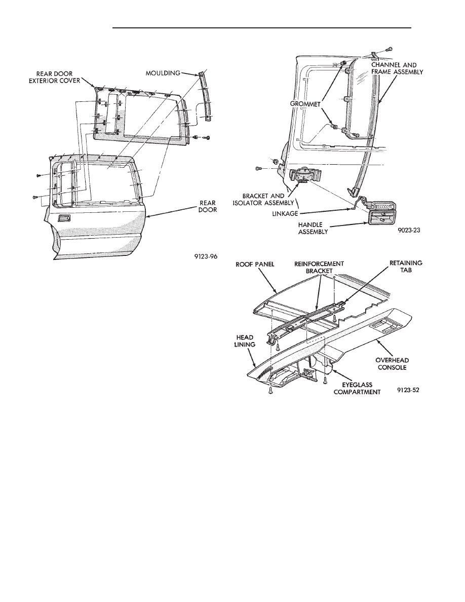
REAR DOOR FIXED WINDOW MODULE
REMOVAL (FIG. 22)
(1) Remove rear door trim panel.
(2) Remove rear door glass.
(3) Remove screws and bolts holding rear door
fixed glass module to door.
(4) Separate fixed glass module from door.
INSTALLATION
Reverse the preceding operation.
OVERHEAD CONSOLE
REMOVAL (FIG. 23)
(1) Remove screws holding overhead console to re-
inforcement bracket.
(2) Slide overhead console rearward to separate re-
inforcement bracket retainer tab from console.
(3) Lower console from roof and disconnect wire
connectors.
INSTALLATION
Reverse The preceding operation.
HEAD LINING
REMOVAL (FIG. 24)
(1) Disconnect battery negative cable.
(2) Pull dome lamp downward to disengage from
retaining ring in head lining. Separate lens from
lamp body and remove bulb. Separate bulb holder
from lamp body. Remove attaching screw holding re-
taining ring to roof bow, if equipped.
(3) Remove screws holding coat hooks to roof above
rear doors.
(4) Remove roof rail and A-pillar mouldings.
(5) Remove screws holding sun visors to roof
header and disconnect wire connector, if equipped.
Remove inboard sun visor hangers.
(6) Remove overhead console, if equipped.
(7) Pull front reading lamp downward to disengage
from retaining ring in head lining and disconnect
wire connector. Remove screws holding retaining
ring to roof header, if equipped.
(8) Remove pinch welt holding headlining to sun
roof opening, if equipped.
(9) Remove inside rear view mirror from wind-
shield bracket if necessary.
Fig. 21 Rear Door Outer Cover—AY-P Body
Fig. 22 Rear Door Fixed Window
Fig. 23 Overhead Console
23 - 142
AY-BODY
Ä
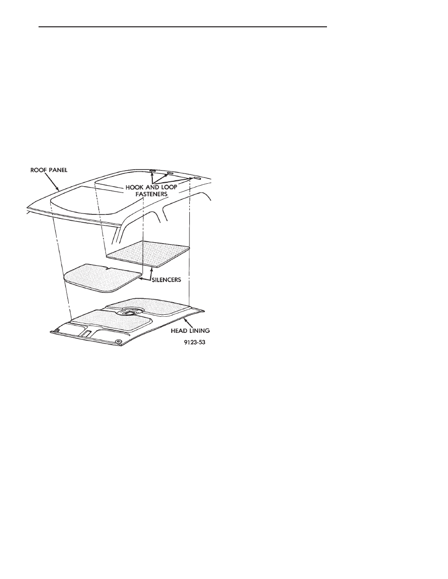
(10) Disengage hook and loop fasteners holding
head lining to roof above rear window and slide head
lining forward about 25 mm (1 in.).
(11) Shift the front of head lining to one side to
pull head lining from behind B-pillar trim. Pull head
lining from behind other B-pillar trim.
(12) Allow front of head lining to drop downward.
Slide head lining forward from behind quarter panel
trim.
(13) Remove head lining from vehicle.
INSTALLATION
Reverse the preceding operation.
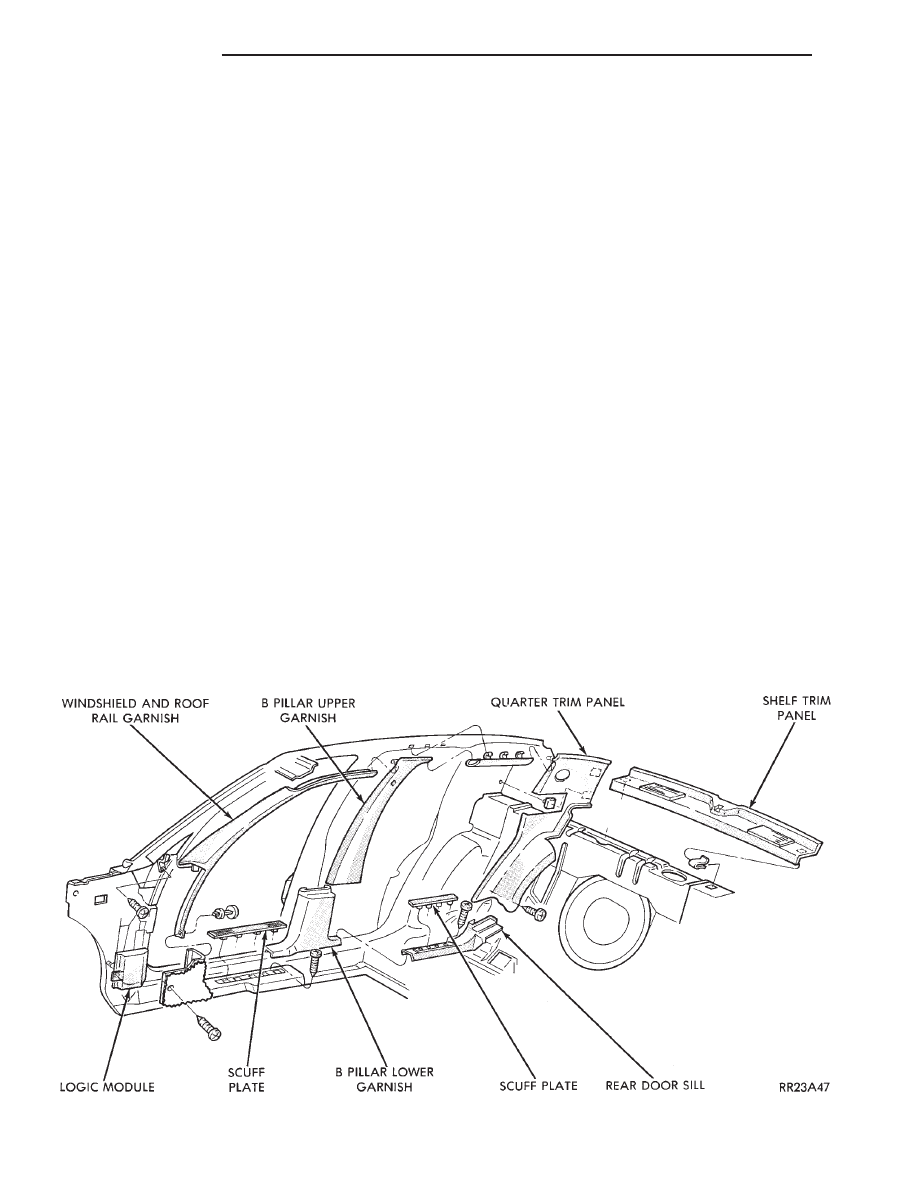
COWL PANEL TRIM AND SCUFF PLATES
COWL PANEL AND DOOR OPENING SCUFF
PLATE REMOVAL (FIG. 25)
(1) Open front door.
(2) Remove screw holding trim panel to cowl, for-
ward of the front door opening.
(3) Remove screws holding scuff plate to door sill.
(4) Separate cowl panel trim and scuff plate from
vehicle.
COWL PANEL AND DOOR OPENING SCUFF
PLATE INSTALLATION
Reverse the preceding operation.
REAR DOOR OPENING SCUFF PLATE
REMOVAL (FIG. 25)
(1) Open rear door.
(2) Remove screws holding scuff plate to door sill.
(3) Separate scuff plate from vehicle.
REAR DOOR OPENING SCUFF PLATE
INSTALLATION
Reverse the preceding operation.
A-PILLAR AND ROOF RAIL MOULDINGS
A-PILLAR MOULDING REMOVAL (FIG. 25)
(1) Open front door.
(2) Disengage clips holding A-pillar moulding to
roof rail above door opening.
(3) Remove push-in fastener holding lower A-pillar
trim to pillar.
(4) Slide A-pillar moulding upward and pull rear-
ward to separate moulding from A-pillar.
A-PILLAR MOULDING INSTALLATION
Reverse the preceding operation.
REAR DOOR ROOF RAIL MOULDING
REMOVAL (FIG. 25)
(1) Open rear door.
(2) Disengage clips holding roof rail moulding to
roof rail above rear door opening.
(3) Separate moulding from vehicle.
REAR DOOR ROOF RAIL MOULDING
INSTALLATION
Reverse the preceding operation.
B-PILLAR TRIM PANEL
REMOVAL (FIG. 25)
(1) Remove roof rail mouldings and scuff plates as
necessary.
(2) Remove shoulder harness turning loop cover.
Remove bolt holding turning loop to B-pillar.
(3) Remove bolt holding seat belt to floor below
B-pillar.
(4) Remove screws holding upper B-pillar trim to
pillar and separate trim from pillar.
(5) Remove screws holding lower b-pillar trim to
pillar and separate trim from pillar.
INSTALLATION
Reverse the preceding operation.
QUARTER TRIM PANEL
REMOVAL (FIG. 25)
(1) Remove roof rail mouldings and scuff plates as
necessary.
(2) Remove shoulder harness turning loop cover.
Remove bolt holding turning loop to quarter panel.
(3) Remove rear seat cushion and back.
(4) Remove fastener holding quarter trim to roof
rail.
(5) Remove screws holding quarter trim panel to
wheelhouse kickup.
Fig. 24 Head Lining—Typical
Ä
AY-BODY
23 - 143
(6) Pull trim panel forward and separate from ve-
hicle.
(7) Remove bolt holding lap belt anchor to floor
and push end of belt through access hole in trim
panel.
INSTALLATION
Reverse the preceding operation.
REAR SHELF TRIM PANEL
REMOVAL (FIG. 25)
(1) Remove one quarter trim panel.
(2) Remove center high mounted stop lamp cover.
Refer to Group 8L, Lamps for instructions.
(3) Disengage clips holding trim to shelf panel and
separate trim from vehicle.
INSTALLATION
Reverse the preceding operation.
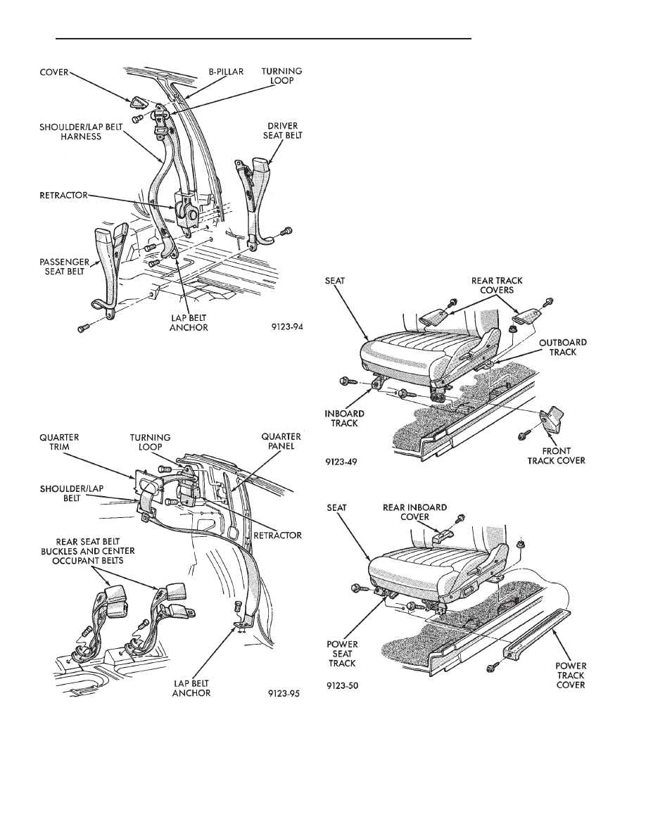
FRONT SEAT BELTS
OUTBOARD SHOULDER HARNESS/LAP BELT
REMOVAL (FIG. 26)
(1) Remove B-pillar trim panel.
(2) Remove bolt holding seat belt retractor to
B-pillar.
(3) Separate retractor from vehicle.
OUTBOARD SHOULDER HARNESS/LAP BELT
INSTALLATION
Reverse the preceding operation.
INBOARD BUCKLE/CENTER OCCUPANT
BELTS REMOVAL (FIG. 26)
Vehicles equipped with front bucket seats with cen-
ter console do not have center occupant belts.
(1) Remove bolt holding inboard buckle/center oc-
cupant belt to floor.
(2) Disconnect seat belt sensor wire connector.
(3) Separate buckle/belt assembly from vehicle.
INBOARD BUCKLE/CENTER OCCUPANT BELT
INSTALLATION
Reverse the preceding operation.
REAR SEAT BELTS
OUTBOARD SHOULDER HARNESS/LAP BELT
REMOVAL (FIG. 27)
(1) Remove quarter trim panel.
(2) Remove bolt holding lap belt to floor at wheel-
house kickup.
(3) Remove bolt holding turning loop to inner
quarter panel.
(4) Remove bolt holding seat belt retractor to quar-
ter panel.
OUTBOARD SHOULDER HARNESS/LAP BELT
INSTALLATION
Reverse the preceding operation.
INBOARD BUCKLE/CENTER OCCUPANT
BELTS REMOVAL (FIG. 27)
(1) Remove rear seat cushion.
(2) Remove bolt holding inboard buckle/center oc-
cupant belt to floor.
Fig. 25 Interior Mouldings, Panels, and Trim Covers
23 - 144
AY-BODY
Ä
(3) Separate buckle/belt assembly from vehicle.
INBOARD BUCKLE/CENTER OCCUPANT BELT
INSTALLATION
Reverse the preceding operation.
FRONT SEATS
REMOVAL (FIG. 28 OR 29)
(1) Position seat full forward.
(2) Remove screws holding rear track riser covers
and separate covers from tracks.
(3) On power seat track, remove outboard track
cover.
(4) Remove inboard seat belt attaching bolt from
floor.
(5) Remove nuts holding seat track to floor.
(6) Position seat full rearward.
(7) Remove door sill scuff plate and disconnect
power seat track wire connector.
(8) Remove bolts holding seat track to cross mem-
ber.
(9) Remove seat from vehicle.
INSTALLATION
Reverse the preceding operation.
REAR SEATS
REAR SEAT CUSHION REMOVAL
(1) Remove bolts holding cushion to floor.
(2) Disconnect center occupant seat belts from
cushion.
Fig. 26 Front Seat Belts
Fig. 27 Rear Seat Belts
Fig. 28 Manual Front Seat—Typical
Fig. 29 Power Front Seat—Typical
Ä
AY-BODY
23 - 145
Нет комментариевНе стесняйтесь поделиться с нами вашим ценным мнением.
Текст