Chrysler Le Baron, Dodge Dynasty, Plymouth Acclaim. Manual — part 47
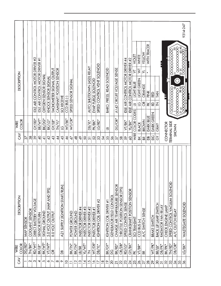
Fig.
2
60-W
ay
PCM
W
iring
Connector
14 - 106
FUEL SYSTEMS
Ä
2.2L TURBO III MULTI-PORT FUEL INJECTION—SERVICE PROCEDURES
INDEX
page
page
Fuel Injector Rail Assembly
. . . . . . . . . . . . . . . . 109
Fuel Injectors
. . . . . . . . . . . . . . . . . . . . . . . . . . 110
Fuel Pressure Regulator
. . . . . . . . . . . . . . . . . . 111
Fuel System Pressure Release Procedure
. . . . . 107
Heated Oxygen Sensor (O
2
Sensor)
. . . . . . . . . 112
Idle Air Control Motor
. . . . . . . . . . . . . . . . . . . . 108
Manifold Absolute Pressure (MAP) Sensor
Service
. . . . . . . . . . . . . . . . . . . . . . . . . . . . . . 111
PCM Service
. . . . . . . . . . . . . . . . . . . . . . . . . . . 111
Throttle Body
. . . . . . . . . . . . . . . . . . . . . . . . . . . 107
Throttle Body Removal
. . . . . . . . . . . . . . . . . . . 108
Throttle Position Sensor (TPS)
. . . . . . . . . . . . . 107
Wastegate and Canister Purge Solenoid Service . 111
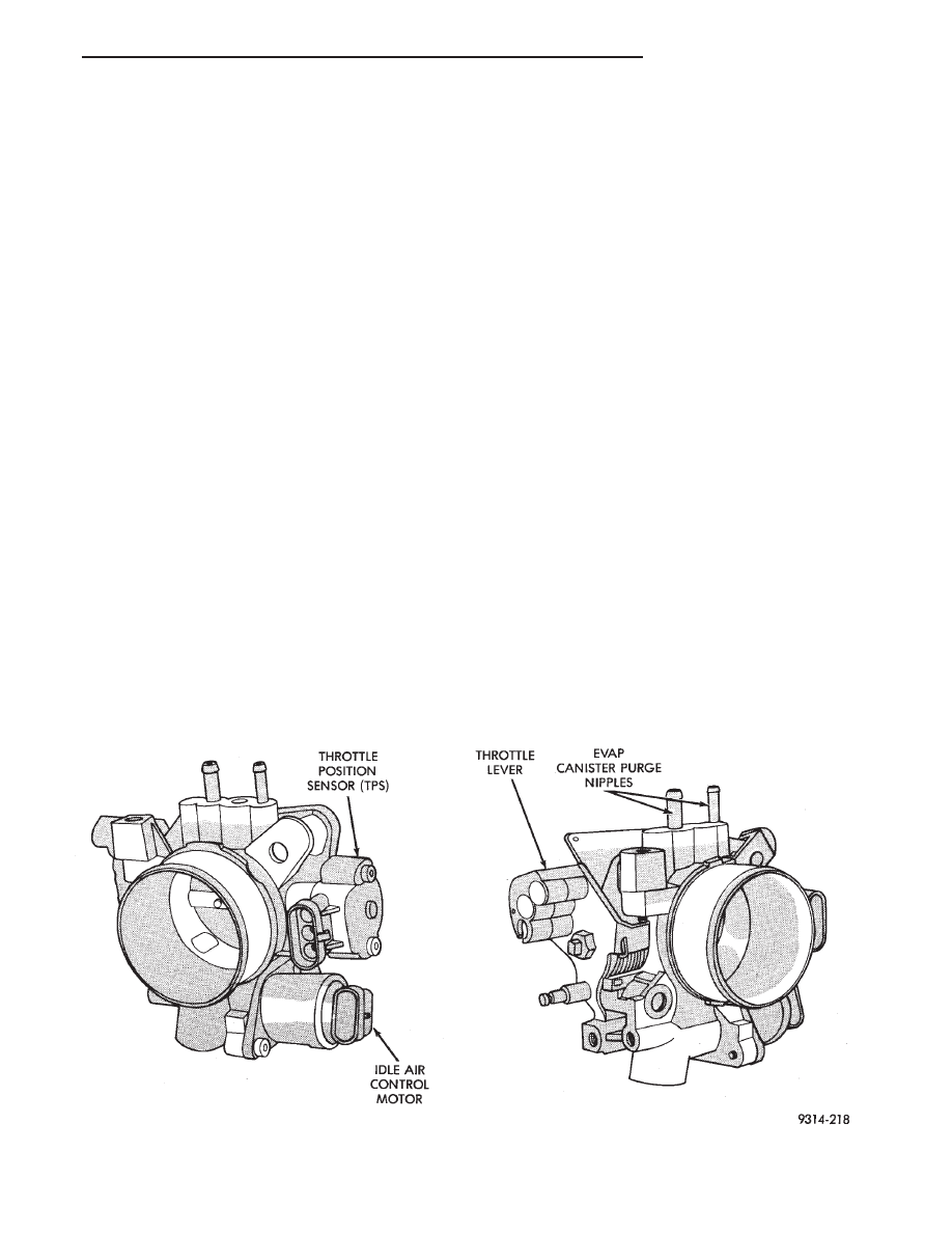
THROTTLE BODY
When servicing throttle body components, always
reassemble components with new O-rings and seals
where applicable (Fig. 1). Never use lubricants on
O-rings or seals, damage may result. If assembly of
component is difficult, use water to aid assembly.
Use care when removing hoses to prevent damage to
hose or hose nipple.
FUEL SYSTEM PRESSURE RELEASE PROCEDURE
CAUTION: The fuel system is under a constant
pressure of approximately 380 kPa (55 psi). Before
servicing the fuel pump, fuel lines, fuel filter, throt-
tle body, or fuel injectors, the fuel system pressure
must be released.
(1) Disconnect negative cable from battery.
(2) Remove fuel filler cap.
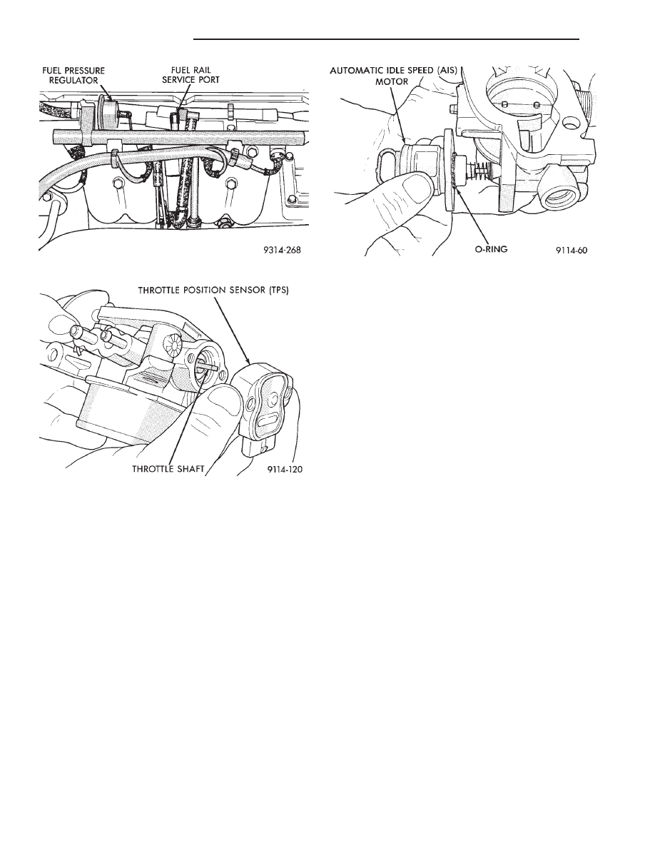
(3) Remove the protective cap from the fuel pres-
sure test port on the fuel rail (Fig. 2).
(4) Place the open end of fuel pressure release
hose, tool number C-4799-1, into an approved gaso-
line container. Connect the other end of hose
C-4799-1 to the fuel pressure test port. Fuel pressure
will bleed off through the hose into the gasoline con-
tainer. Fuel gauge C-4799-A contains hose C-4799-1.
(5) Continue fuel system service.
THROTTLE POSITION SENSOR (TPS)
REMOVAL
(1) Disconnect the negative cable from the battery.
(2) Disconnect harness connector from throttle po-
sition sensor (Fig. 3).
(3) Remove
throttle
position
sensor
mounting
screws.
(4) Lift throttle position sensor off throttle shaft.
Fig. 1 Throttle Body
Ä
FUEL SYSTEMS
14 - 107
INSTALLATION
(1) Install throttle position sensor on throttle shaft.
Install mounting screws. Tighten screws to 2 N
Im (17
in. lbs.) torque.
(2) Attach harness connector to sensor.
(3) Connect negative cable to negative post of the
battery.
IDLE AIR CONTROL MOTOR
REMOVAL
(1) Disconnect negative cable from battery.
(2) Disconnect harness connector from idle air con-
trol motor (Fig. 4).
(3) Remove idle air control motor mounting screws.
(4) Remove the motor from throttle body. Ensure the
O-ring is was removed with the idle air control motor.
INSTALLATION
(1) New idle air control motors have a new O-ring
installed on them. If pintle measures more than 1
inch (25 mm) it must be retracted by using the IDLE
AIR CONTROL MOTOR OPEN/CLOSE mode of the
DRBII scan tool.
(2) Carefully place idle air control motor into
throttle body.
(3) Install mounting screws. Tighten screws to 2
N
Im (17 in. lbs.) torque.
(4) Connect harness connector to motor.
(5) Connect negative cable to battery.
THROTTLE BODY REMOVAL
(1) Disconnect negative cable from battery.
(2) Remove clamp from air hose. Remove hose (Fig.
5).
(3) Remove accelerator cable.
(4) Disconnect idle air control motor and throttle
position sensor (TPS) electrical connectors (Fig. 6).
(5) Disconnect vacuum hoses from throttle body.
(6) Remove throttle body to intake manifold at-
taching nuts (2).
(7) Remove throttle body and gasket.
INSTALLATION
(1) Install throttle body with new gasket.
(2) Install throttle body attaching nuts. Tighten
nuts to 25 N
Im (225 in. lbs.) torque.
(3) Connect vacuum hoses to the throttle body.
(4) Attach harness connectors to the throttle posi-
tion sensor (TPS) and the idle air control motor.
(5) Install throttle and speed control cables (if ap-
plicable).
(6) Install throttle body intake air hose. Tighten
clamp to 4 N
Im (30 in. lbs.) torque.
(7) Connect negative cable to battery.
Fig. 4 Idle Air Control Motor
Fig. 2 Fuel Pressure Test Port
Fig. 3 Throttle Position Sensor
14 - 108
FUEL SYSTEMS
Ä

FUEL INJECTOR RAIL ASSEMBLY
WARNING: THE 2.2L TURBO III FUEL SYSTEM IS
UNDER A CONSTANT PRESSURE OF APPROXI-
MATELY 380 KPA (55 PSI). PERFORM FUEL PRES-
SURE RELEASE PROCEDURE BEFORE SERVICING
THE FUEL RAIL OR FUEL INJECTORS.
REMOVAL
(1) Perform fuel system pressure release procedure.
(2) Disconnect negative battery cable.
CAUTION: Place a shop towel should under the fuel
hoses to catch any fuel spillage.
(3) Remove quick connect fittings from the chassis
fuel tubes (Fig. 7). Refer to Quick Connect Fittings
in the Fuel Delivery Section of this manual.
(4) Disconnect the vacuum hose from the fuel pres-
sure regulator (Fig. 8).
(5) Disconnect the fuel injector wiring harness
from the main harness.
(6) Place oil separator bracket out of the way and
remove the fuel rail support bracket screws.
(7) Remove the fuel rail and injector assembly by
pulling rail so that the injectors come straight out of
their ports. Do not damage the rubber injector
O-rings after removing the fuel rail.
Do not remove fuel injectors until fuel rail assem-
bly has been completely removed from the vehicle.
Fig. 7 Quick Connect Fittings
Fig. 8 Fuel Rail Fasteners
Fig. 5 Air Cleaner Assembly
Fig. 6 Throttle Body Assembly
Ä
FUEL SYSTEMS
14 - 109
Нет комментариевНе стесняйтесь поделиться с нами вашим ценным мнением.
Текст