Chrysler Le Baron, Dodge Dynasty, Plymouth Acclaim. Manual — part 48
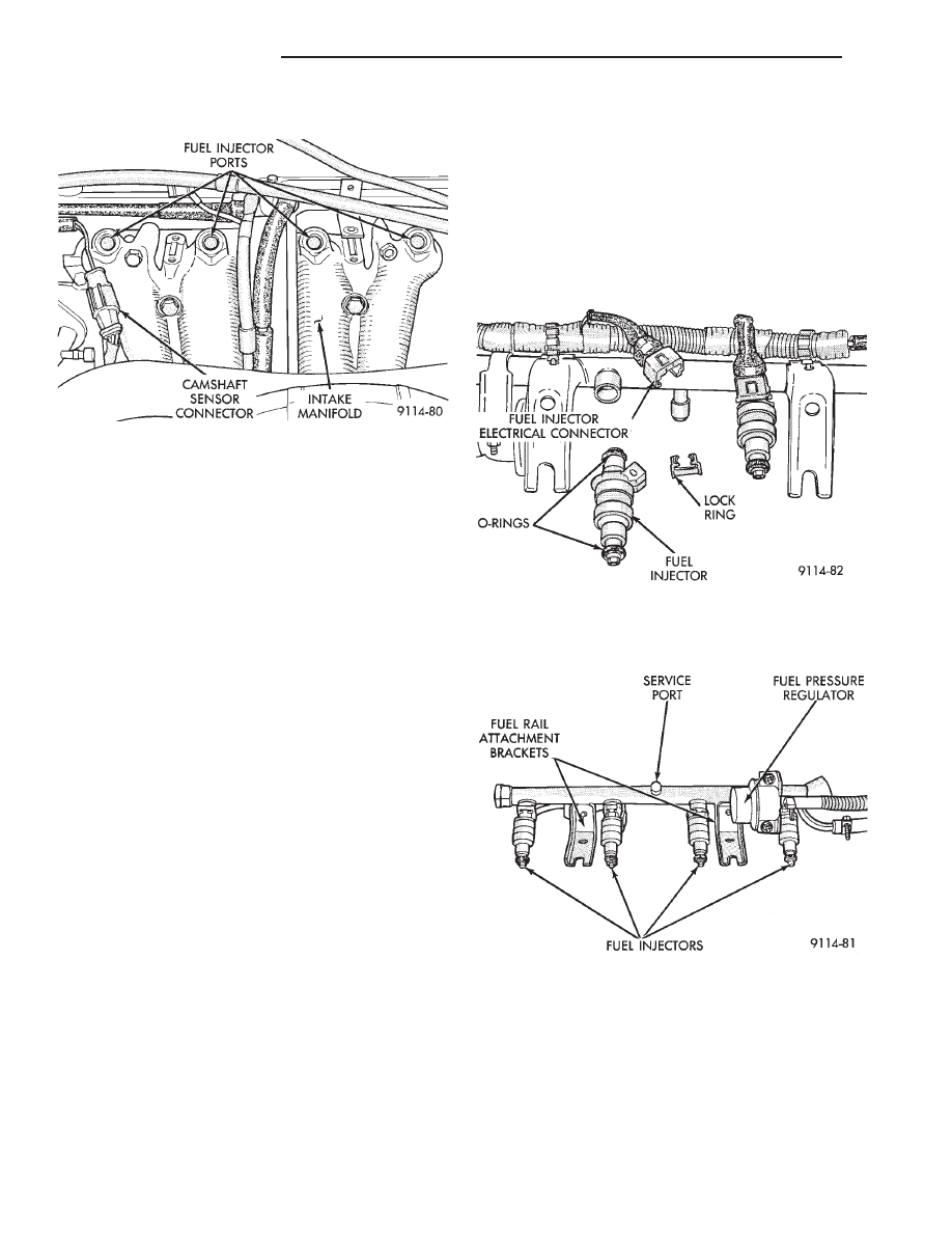
(8) Cover or plug the injector ports with while ser-
vicing the injectors (Fig. 9).
INSTALLATION
(1) Ensure the injectors are seated into the re-
ceiver cup, with the lock ring in place.
(2) Ensure the injector wiring connectors are fully
inserted into the fuel injectors.
(3) Make sure the injector holes are clean and all
plugs have been removed (Fig. 9).
(4) Lubricate the injector O-rings with a drop of
clean engine oil.
(5) Install the injector assemblies into their holes
and install the attaching bolts. Draw the fuel rail as-
sembly evenly into the intake manifold, making sure
each injector enters its own hole. The oil separator
bracket must be on top of the fuel rail bracket (Fig.
8).
(6) Once all injectors are evenly seated, tighten the
fuel rail attaching bolts to 23 N
Im (200 in. lbs.)
torque.
(7) Connect the fuel injector wiring harness to the
main harness.
(8) Lubricate the ends of the chassis tubes with
clean 30 weight engine oil.
(9) Connect fuel hose quick connect fittings to the
chassis fuel tubes. Pull on the fittings to ensure com-
plete connection.
Refer to Quick Connect Fittings in the Fuel Deliv-
ery Section of this group.
(10) Connect the vacuum hose to the fuel pressure
regulator.
(11) Connect negative cable to battery.
CAUTION: When using the ASD Fuel System Test,
the Auto Shutdown (ASD) Relay remains energized
for either 7 minutes, until the test is stopped, or un-
til the ignition switch is turned to the Off position.
(12) With the DRBII scan tool the ASD Fuel Sys-
tem Test to pressurize the fuel system to check for
leaks.
FUEL INJECTORS
Remove the fuel rail to service the injectors. Refer
to Fuel Injector Rail Assembly in this section.
REMOVAL
(1) Disconnect injector electrical connector from in-
jector. (Fig. 10).
(2) Position fuel rail assembly so that the fuel in-
jectors are easily accessible (Fig. 11).
(3) Remove injector lock ring off the fuel rail and
injector. Pull injector straight out of fuel rail receiver
cup (Fig. 11).
(4) Check injector O-ring for damage. If O-ring is
damaged, it must be replaced. If injector is reused, a
protective cap must be installed on the injector tip to
prevent damage.
(5) Repeat for remaining injectors.
Fig. 9 Fuel Injector Ports
Fig. 10 Fuel Rail and Injector Assembly
Fig. 11 Servicing Fuel Injectors
14 - 110
FUEL SYSTEMS
Ä
INSTALLATION
(1) Before installing an injector, the rubber O-ring
must be lubricated with a drop of clean engine oil to aid
in installation.
(2) Being careful not to damage the O-ring, install
injector top end into fuel rail receiver cup.
(3) Install injector lock ring by sliding open end into
slot of the injector and onto the receiver cup ridge into
the side slots of ring (Fig. 11).
(4) Repeat steps for remaining injectors.
(5) Install injector wiring harness to injectors. Place
harness into retaining clips.
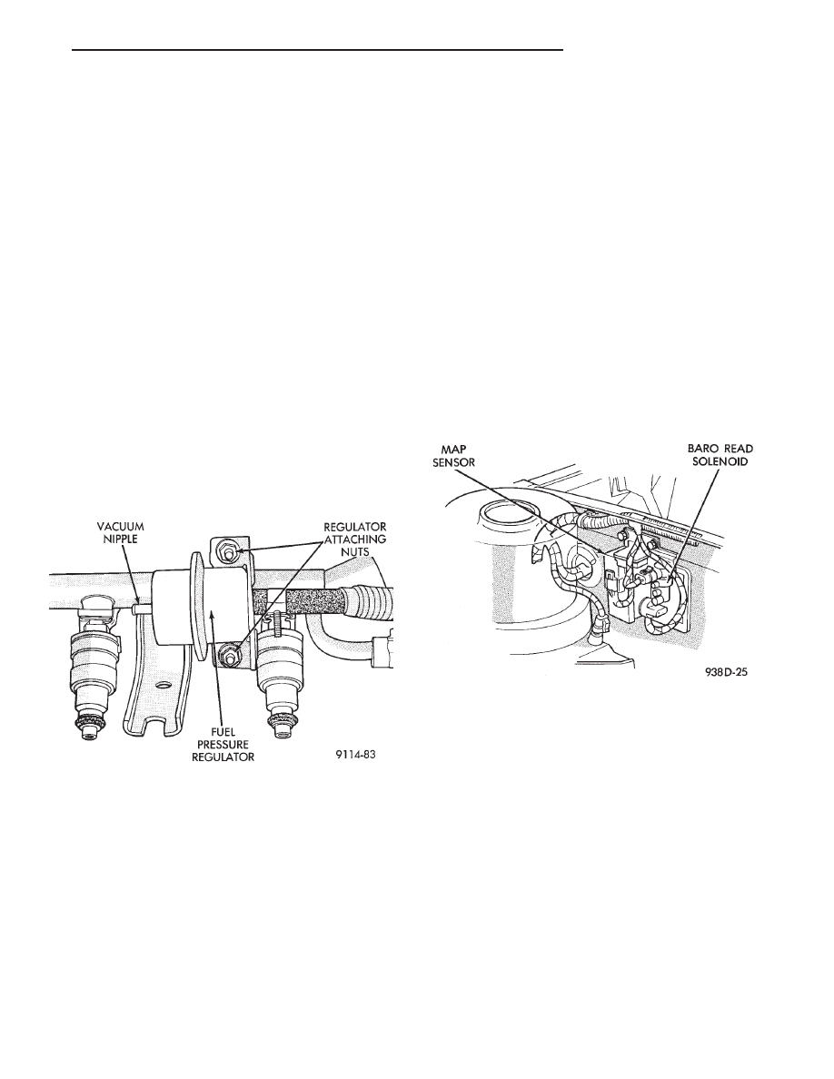
FUEL PRESSURE REGULATOR
WARNING: THE 2.2L TURBO III FUEL SYSTEM IS
UNDER A CONSTANT PRESSURE OF APPROXI-
MATELY 380 KPA (55 PSI). PERFORM FUEL PRES-
SURE RELEASE PROCEDURE BEFORE SERVICING
THE FUEL PRESSURE REGULATOR.
REMOVAL
(1) Perform fuel system pressure release procedure.
(2) Disconnect negative cable from battery.
(3) Disconnect vacuum hose from fuel pressure regu-
lator (Fig. 12).
Place a shop towel under fuel pressure regula-
tor to absorb any fuel spillage.
(4) Loosen fuel hose clamp and remove fuel return
hose.
(5) Remove fuel pressure regulator mounting nuts.
Remove fuel pressure regulator from rail (Fig. 12).
Check O-Ring for damage. If O-Ring is damaged it
must be replaced.
INSTALLATION
(1) Lubricate O-ring with a drop of clean engine oil.
Install O-ring into the receiver cup on fuel rail.
(2) Install fuel pressure regulator mounting nuts.
Tighten nuts to 7 N
Im (65 in. lbs.) torque.
(3) Connect fuel return hose to pressure regulator.
Tighten hose clamp to 1 N
Im (10 in. lbs.) torque (Fig.
12).
(4) Install vacuum hose on fuel pressure regulator.
(5) Connect negative cable to battery.
CAUTION: When using the ASD Fuel System Test,
the Auto Shutdown (ASD) Relay remains energized
for either 7 minutes, until the test is stopped, or un-
til the ignition switch is turned to the Off position.
(6) With the DRBII scan tool the ASD Fuel System
Test to pressurize system and check for leaks.
MANIFOLD ABSOLUTE PRESSURE (MAP) SENSOR
SERVICE
(1) Remove vacuum hose from MAP sensor (Fig.
13)
(2) Remove MAP sensor mounting screws (Fig. 13).
(3) Remove electrical connector. Remove sensor.
(4) Reverse the above procedure for installation.
WASTEGATE AND CANISTER PURGE SOLENOID
SERVICE
(1) Remove vacuum hoses from sensors (Fig. 14).
(2) Disconnect electrical connector from solenoids
(Fig. 14).
(3) Remove solenoid pack mounting nut. Remove
solenoid pack.
(4) Depress tab on top of solenoid to be replaced
and slide the solenoid downward out of mounting
bracket.
(5) Reverse above procedure to install.
PCM SERVICE
(1) Remove air cleaner duct from PCM.
(2) Remove battery.
(3) Remove PCM mounting screws (Fig. 15).
(4) Disconnect the 60-way wiring connector. Re-
move the PCM.
(5) Reverse the above procedure for installation.
Fig. 13 Manifold Absolute Pressure Sensor
Fig. 12 Servicing Fuel Pressure Regulator
Ä
FUEL SYSTEMS
14 - 111
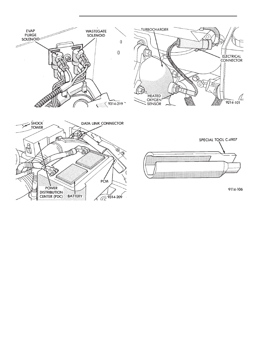
HEATED OXYGEN SENSOR (O
2
SENSOR)
The oxygen sensor is installed in the exhaust man-
ifold (Fig. 16).
CAUTION: Do not pull on the oxygen sensor wires
when disconnecting the electrical connector.
WARNING: THE EXHAUST MANIFOLD MAY BE EX-
TREMELY HOT. USE CARE WHEN SERVICING THE
OXYGEN SENSOR.
(1) Disconnect oxygen sensor electrical connector.
(2) Remove sensor using Tool C-4907 (Fig. 17).
Slightly tightening the sensor can ease removal.
When the sensor is removed, the exhaust manifold
threads must be cleaned with an 18 mm X 1.5 + 6E
tap. If using original sensor, coat the threads with
Loctite 771-64 anti-seize compound or equivalent.
New sensors are packaged with compound on the
threads and do not require additional compound.
Tighten the sensor to 27 N
Im (20 ft. lbs.) torque.
Fig. 14 Solenoid Mounting
Fig. 15 PCM
Fig. 16 Heated Oxygen Sensor
Fig. 17 Oxygen Sensor Socket
14 - 112
FUEL SYSTEMS
Ä
3.0L MULTI-PORT FUEL INJECTION—SYSTEM OPERATION
INDEX
page
page
Air Conditioning (A/C) Clutch Relay (AA, AG, AJ
Body)—PCM Output
. . . . . . . . . . . . . . . . . . . . 118
Air Conditioning (A/C) Clutch Relay (AC Body)
—PCM Output
. . . . . . . . . . . . . . . . . . . . . . . . 118
Air Conditioning Switch Sense (AA, AG, AJ
Body)—PCM Input
. . . . . . . . . . . . . . . . . . . . . 115
Air Conditioning Switch Sense (AC Body)—PCM
Input
. . . . . . . . . . . . . . . . . . . . . . . . . . . . . . . . 115
Auto Shutdown (ASD) Relay and Fuel Pump
Relay—PCM Output
. . . . . . . . . . . . . . . . . . . . 119
Battery Voltage—PCM Input
. . . . . . . . . . . . . . . 115
Brake Switch—PCM Input
. . . . . . . . . . . . . . . . . 115
CCD Bus
. . . . . . . . . . . . . . . . . . . . . . . . . . . . . . 113
Data Link Connector—PCM Output
. . . . . . . . . . 120
Distributor Pick-Up—PCM Input
. . . . . . . . . . . . . 115
Duty Cycle Evap Canister Purge Solenoid
—PCM Output
. . . . . . . . . . . . . . . . . . . . . . . . 119
Engine Coolant Temperature Sensor
—PCM Input
. . . . . . . . . . . . . . . . . . . . . . . . . 115
Fuel Injectors—PCM Output
. . . . . . . . . . . . . . . 120
Fuel Pressure Regulator
. . . . . . . . . . . . . . . . . . 124
Fuel Supply Circuit
. . . . . . . . . . . . . . . . . . . . . . 123
General Information
. . . . . . . . . . . . . . . . . . . . . . 113
Generator Field—PCM Output
. . . . . . . . . . . . . . 118
Heated Oxygen Sensor (O
2
Sensor)
—PCM Input
. . . . . . . . . . . . . . . . . . . . . . . . . 116
Idle Air Control Motor—PCM Output
. . . . . . . . . 119
Ignition Coil—PCM Output
. . . . . . . . . . . . . . . . . 121
Malfunction Indicator Lamp (Check Engine
Lamp)—PCM Output
. . . . . . . . . . . . . . . . . . . 120
Manifold Absolute Pressure (MAP) Sensor
—PCM Input
. . . . . . . . . . . . . . . . . . . . . . . . . 116
Modes of Operation
. . . . . . . . . . . . . . . . . . . . . . 121
Park/Neutral Switch—PCM Input
. . . . . . . . . . . . 117
Part Throttle Unlock Solenoid—PCM Output
. . . 121
Powertrain Control Module
. . . . . . . . . . . . . . . . . 113
Radiator Fan Relay—PCM Output
. . . . . . . . . . . 121
Speed Control Solenoids—PCM Output
. . . . . . . 121
Speed Control—PCM Input
. . . . . . . . . . . . . . . . 117
System Diagnosis
. . . . . . . . . . . . . . . . . . . . . . . 113
Tachometer—PCM Output
. . . . . . . . . . . . . . . . . 121
Throttle Body
. . . . . . . . . . . . . . . . . . . . . . . . . . . 123
Throttle Position Sensor (TPS)—PCM Input
. . . . 117
Transaxle Control Module—PCM Output
. . . . . . 120
Vehicle Speed and Distance Input—PCM Input
. 118
Vehicle Speed Sensor—PCM Input
. . . . . . . . . . 118
GENERAL INFORMATION
The 3.0L engine uses a sequential Multi-Port Elec-
tronic Fuel Injection system (Fig. 1). The MPI system
is computer regulated and provides precise air/fuel
ratios for all driving conditions.
The MPI system is operated by the powertrain con-
trol module (PCM).
The PCM regulates ignition timing, air-fuel ratio,
emission control devices, cooling fan, charging sys-
tem, idle speed and speed control. Various sensors
provide the inputs necessary for the PCM to correctly
operate these systems. In addition to the sensors,
various switches also provide inputs to the PCM.
All inputs to the PCM are converted into signals.
The PCM can adapt its programming to meet chang-
ing operating conditions.
Fuel is injected into the intake port above the in-
take valve in precise metered amounts through elec-
trically
operated
injectors.
The
PCM
fires
the
injectors in a specific sequence. The PCM maintains
an air fuel ratio of 14.7 parts air to 1 part fuel by
constantly adjusting injector pulse width. Injector
pulse width is the length of time the injector is ener-
gized.
The PCM adjusts injector pulse width by opening
and closing the ground path to the injector. Engine
RPM (speed) and manifold absolute pressure (air
density) are the primary inputs that determine injec-
tor pulse width.
SYSTEM DIAGNOSIS
The powertrain control module (PCM) tests many
of its own input and output circuits. If a fault is
found in a major system, the information is stored in
memory. Technicians can display fault information
through the malfunction indicator lamp (instrument
panel Check Engine lamp) or by connecting the
DRBII scan tool. For diagnostic trouble code informa-
tion, refer to the 3.0 Multi-Port Fuel Injection—On-
Board Diagnostics section of this group.
CCD BUS
Various modules exchange information through a
communications port called the CCD Bus. The pow-
ertrain control module (PCM) transmits the malfunc-
tion indicator (instrument panel check engine lamp)
On/Off signal, engine RPM and vehicle load data on
the CCD Bus.
POWERTRAIN CONTROL MODULE
The powertrain control module (PCM) is a digital
computer containing a microprocessor (Fig. 2). The
PCM receives input signals from various switches
and sensors that are referred to as PCM Inputs.
Based on these inputs, the PCM adjusts various en-
gine and vehicle operations through devices referred
to as PCM Outputs.
PCM Inputs:
• Air Conditioning Controls
• Battery Voltage
• Brake Switch
Ä
FUEL SYSTEMS
14 - 113
Нет комментариевНе стесняйтесь поделиться с нами вашим ценным мнением.
Текст