Chrysler Le Baron, Dodge Dynasty, Plymouth Acclaim. Manual — part 13
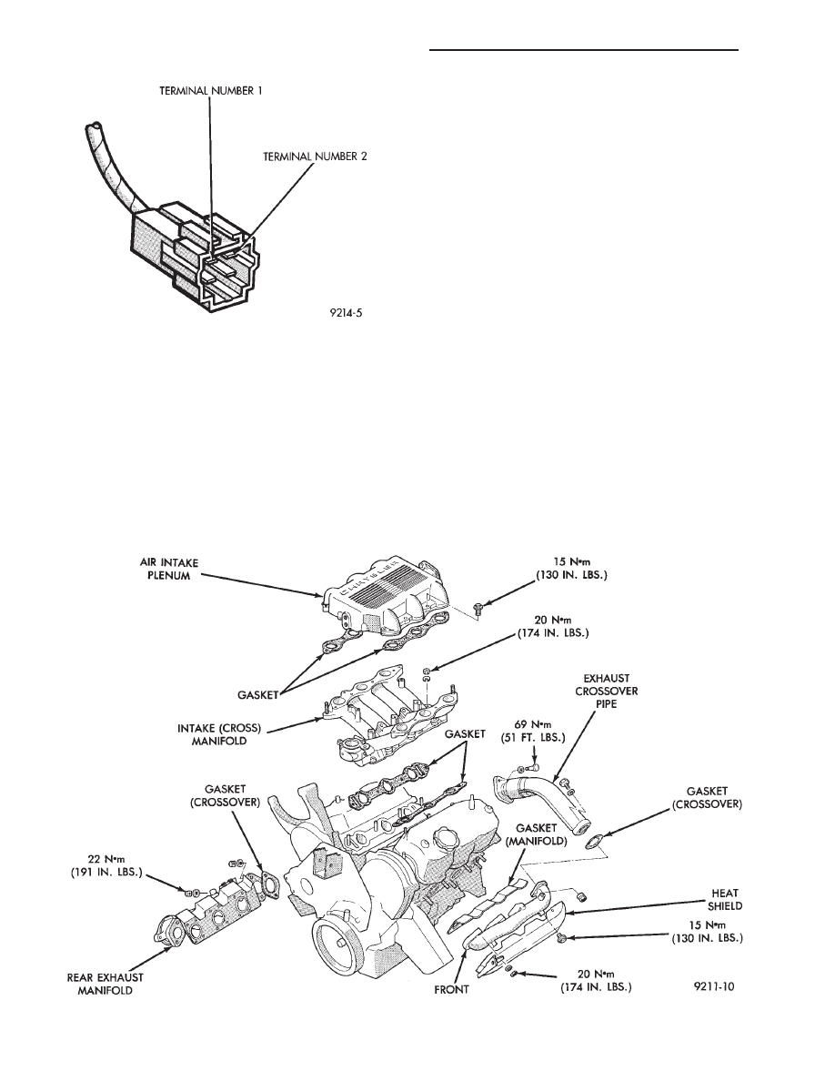
The exhaust manifolds are made of ductile cast
iron with the front bank and rear bank independent
of each other. The exhaust from the front bank ex-
haust manifold is led through on exhaust crossover
pipe to be combined with the rear bank exhaust at
the exhaust outlet to the exhaust pipe (Fig. 2).
INTAKE PLENUM/MANIFOLD
REMOVAL
(1) Perform fuel system pressure release procedure
(before attempting any repairs).
(2) Disconnect negative battery cable. Drain cooling
system. See Cooling System, Group 7.
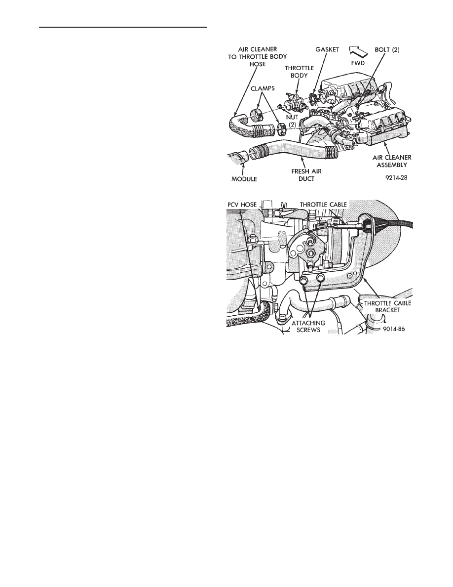
(3) Remove air cleaner to throttle body hose (Fig. 3).
FUEL SYSTEM PRESSURE RELEASE PROCE-
DURE
The MPI fuel system is under a constant pres-
sure of about 330 kPa (48 psi). Before servicing
the fuel pump, fuel lines, fuel filter, throttle body
or fuel injector, the fuel system pressure must be
released.
(a) Loosen fuel filler cap to release fuel tank pres-
sure.
(b) Disconnect injector wiring harness from engine
harness.
(c) Connect a jumper wire to ground terminal
Number 1 of the injector harness (Fig. 1) to engine
ground.
(d) Connect a jumper wire to the positive terminal
Number 2 of the injector harness (Fig. 1) and touch
the battery positive post for no longer than 5 seconds.
This releases system pressure.
Fig. 1 Injector Harness Connector
Fig. 2 Intake and Exhaust Manifolds— 3.0L Engine
11 - 14
EXHAUST SYSTEM AND INTAKE MANIFOLD
Ä
(e) Remove jumper wires.
(f) Continue fuel system service.
(4) Remove throttle cable and transaxle kickdown
linkage (Fig. 4).
(5) Remove automatic idle speed (AIS) motor and
throttle position sensor (TPS) wiring connectors from
throttle body (Fig. 5).
(6) Remove vacuum hose harness from throttle body
(Fig. 5).
(7) Remove PCV and Brake booster hoses from Air
Intake Plenum.
(8) Remove ignition coil from intake plenum (Fig. 6).
(9) Remove wiring connectors from coolant tempera-
ture sensor (Fig. 7).
(10) Remove vacuum connections from air intake
plenum vacuum connector.
(11) Remove fuel hoses from fuel rail (Fig. 7).
WARNING: WRAP SHOP TOWELS AROUND HOSES
TO CATCH ANY GASOLINE SPILLAGE.
(12) Remove (8) Fasteners from Air Intake Plenum
to Intake Manifold (Fig. 8).
(13) Remove air intake plenum (Fig. 9).
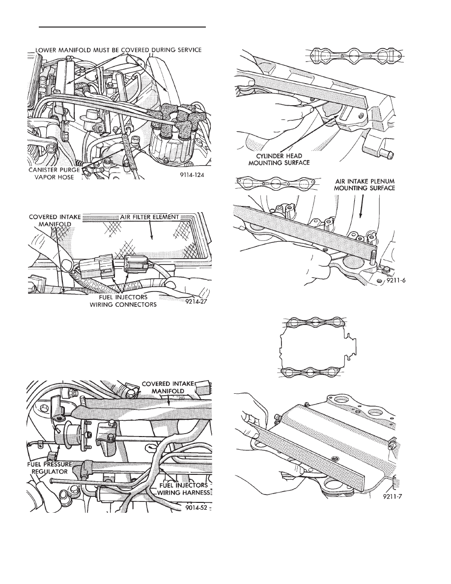
(14) Cover intake manifold with suitable cover when
servicing.
(15) Remove vacuum hoses from fuel rail and fuel
pressure regulator (Fig. 10).
(16) Disconnect Fuel Injector wiring harness from
engine wiring harness (Fig. 11).
(17) Remove fuel pressure regulator attaching bolts
and remove regulator from rail (Fig. 12). Be careful
not to damage the rubber injector O-rings upon
removal from the ports.
(18) Remove fuel rail attaching bolts and lift fuel rail
assembly from intake manifold.
(19) Separate radiator hose from thermostat hous-
ing and heater hose from heater pipe.
(20) Remove (8) nut and washer assemblies and
remove intake manifold (Fig. 2).
INSPECTION
Check for:
• Damage and cracks of each section (Fig. 13).
• Clogged water passages in end cross overs.
• Check for distortion of the cylinder head mounting
surface using a straightedge and thickness gauge (Fig.
14). Refer to (Fig. 15) for Specifications.
INSTALLATION
(1) Position new intake manifold gaskets on cylinder
head and install intake (cross) manifold.
(2) Install (8) nuts and washers and tighten in
several steps in order shown in (Fig. 16) to 20 N
Im
(174 in. lbs.).
(3) Make sure the injector holes are clean and all
plugs have been removed.
(4) Lube injector O-ring with a drop of clean en-
gine oil to ease installation.
(5) Put the tip of each injector into their ports.
Push the assembly into place until the injectors are
seated in the ports.
(6) Install the (3) fuel rail attaching bolts and
torque to 13 N
Im (115 in. lbs.).
(7) Install fuel pressure regulator onto fuel rail. In-
stall attaching bolts to intake manifold. Torque reg-
ulator nuts and bracket bolts to 10 N
Im (95 in. lbs.)
(Fig. 12).
(8) Install fuel supply and return tube hold-down
bolt and the vacuum crossover tube hold-down bolt
and torque to 10 N
Im (95 in. lbs.).
(9) Connect fuel injector wiring harness to engine
wiring harness (Fig. 11).
(10) Connect vacuum harness to fuel pressure reg-
ulator and fuel rail assembly (Fig. 10).
(11) Remove covering from lower intake manifold
and clean surface.
(12) Place intake manifold gaskets with beaded
sealant side up on lower manifold. Put air intake in
Fig. 3 Throttle Body Assembly 3.0L
Fig. 4 Throttle Cable Attachment
Ä
EXHAUST SYSTEM AND INTAKE MANIFOLD
11 - 15

place. Install attaching fasteners (8) and tighten in
several steps in sequence shown (Fig. 17) to 13 N
Im
(115 in. lbs.).
(13) Connect fuel line to fuel rail (Fig. 7). Torque
hose clamps to 1 N
Im (10 in. lbs.).
(14) Connect vacuum harness to air intake ple-
num.
(15) Connect coolant temperature sensor electrical
connector to sensor (Fig. 7).
(16) Connect PCV and brake booster supply hose
to intake plenum.
(17) Connect automatic idle speed (AIS) motor and
throttle position sensor (TPS) electrical connectors
(Fig. 5).
(18) Connect vacuum vapor harness to throttle
body (Fig. 5).
(19) Install throttle cable and transaxle kickdown
linkage (Fig. 4).
(20) Install air inlet hose assembly (Fig. 3).
(21) Install radiator to thermostat housing hose
and heater hose to heater pipe nipple.
(22) Fill cooling system, see Refilling System in
Cooling, Group 7.
(23) Connect negative battery cable.
(24) With the DRBII Scan Tool use ASD Fuel Sys-
tem Test to pressurize system to check for leaks.
Fig. 5 Electrical and Vacuum Connections to
Throttle Body
Fig. 6 Ignition Coil Removal
Fig. 7 Coolant Temperature Sensor Electrical
Connections
Fig. 8 Air Intake Plenum to Intake Manifold
Attaching Bolts
Fig. 9 Removing Air Intake Plenum
11 - 16
EXHAUST SYSTEM AND INTAKE MANIFOLD
Ä
CAUTION: When using the ASD Fuel System Test,
the Auto Shutdown (ASD) relay will remain ener-
gized for 7 minutes or until the ignition switch is
turned to the OFF position, or Stop All Test is se-
lected.
Fig. 13 Check Intake (Cross) Manifold Mounting
Surface
Fig. 14 Check Intake Plenum Mounting Surfaces
Fig. 10 Vacuum Connections for Fuel Rail and Fuel
Pressure Regulator
Fig. 11 Fuel Injector Wiring Harness
Fig. 12 Fuel Pressure Regulator to Fuel Rail
Assembly
Ä
EXHAUST SYSTEM AND INTAKE MANIFOLD
11 - 17
Нет комментариевНе стесняйтесь поделиться с нами вашим ценным мнением.
Текст