Chrysler Le Baron, Dodge Dynasty, Plymouth Acclaim. Manual — part 12

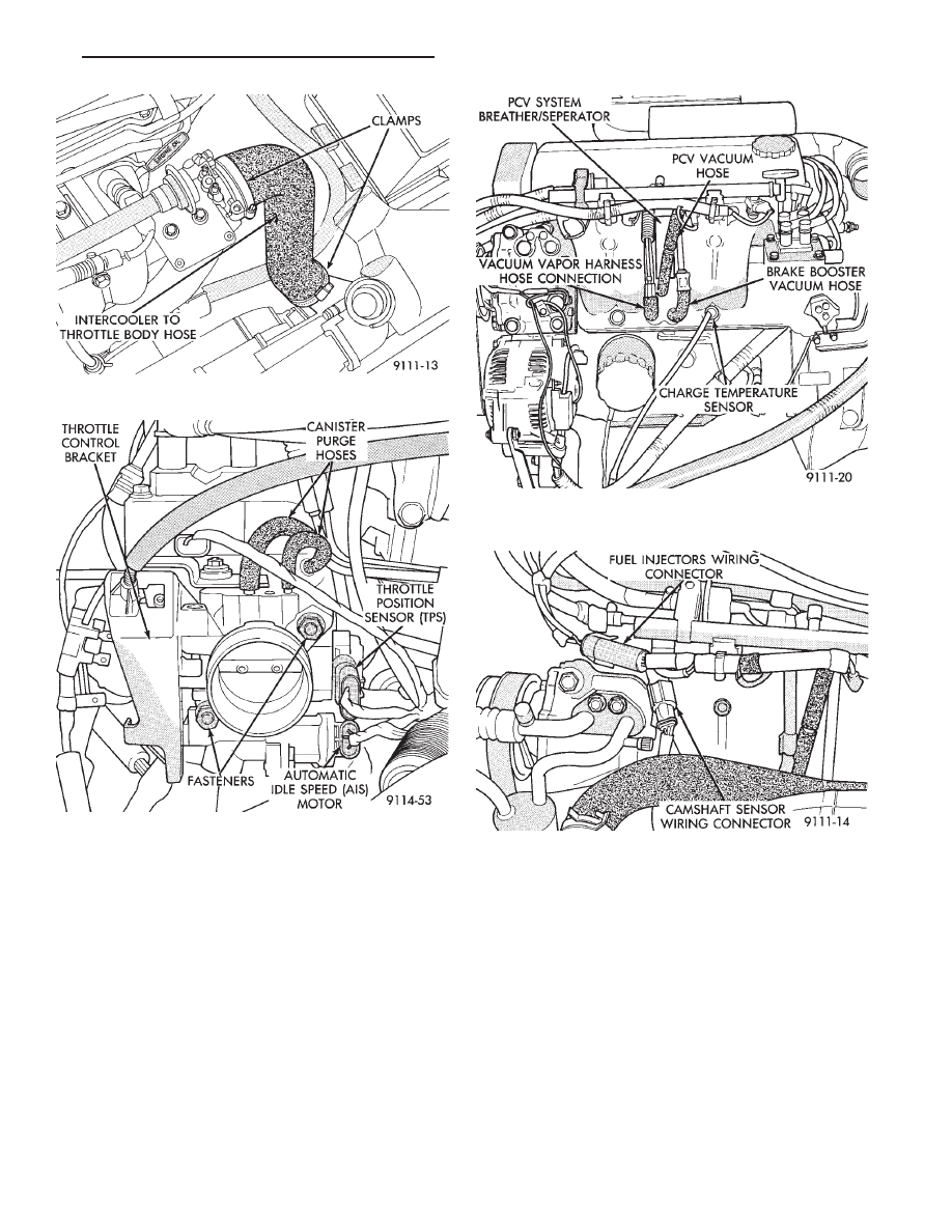
(7) Disconnect Intercooler to throttle body outlet
hose. Disconnect vacuum hoses from throttle body
and remove harness (Fig. 5).
(8) Disconnect automatic idle speed (AIS) motor
and throttle position sensor (TPS) wiring connectors
(Fig. 6).
(9) Remove PCV Breather/Separator box and vac-
uum harness assembly. Remove brake booster, vac-
uum vapor harness and fuel pressure regulator
harness from intake manifold (Fig. 7).
(10) Disconnect Fuel Injector Wiring Connector
(Fig. 8). Charge Temperature Wiring Connector (Fig.
7).
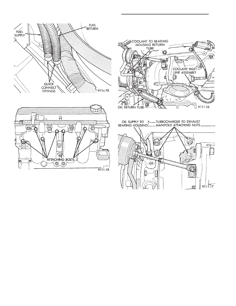
(11) Remove fuel supply and return hose quick
connect at fuel tube assembly (Fig. 9).
WARNING: WRAP SHOP TOWELS AROUND HOSES
TO CATCH ANY GASOLINE SPILLAGE.
(12) Remove 8 intake manifold screws and washer
assemblies and remove intake manifold (Fig. 10).
INSTALLATION
Before installing manifold. Refer to Cleaning and
Inspection of this section to check manifold for dam-
age.
(1) Install new intake manifold gasket and intake
manifold onto cylinder head and tighten fasteners to
23 N
Im (200 in. lbs.) torque (Fig. 10).
(2) Install PCV Breather/Separator box and vac-
uum harness assembly. Connect brake booster, vac-
uum vapor harness and vacuum hose to fuel pressure
regulator (Fig. 7).
Fig. 1 Air Cleaner and Throttle Body
Assembly—Turbo III Engine
Fig. 2 Radiator to Cylinder Head Hose
Fig. 3 Distributorless Ignition Coil (DIS) Location
Fig. 4 Accelerator and Speed Control Cables
11 - 10
EXHAUST SYSTEM AND INTAKE MANIFOLD
Ä
(3) Inspect quick connect fittings for damage, re-
place if necessary Refer to Fuel System, Group 14 for
procedure. Lube tube with clean 30w engine oil, Con-
nect fuel supply and return hoses to chassis tube as-
sembly. Check connection by pulling on connector to
insure it locked into position (Fig. 9).
(4) Connect Fuel Injector (Fig. 8), and Charge
Temperature Sensor wiring connectors (Fig. 7).
INTAKE MANIFOLD
(5) Connect Automatic Idle Speed (AIS) and Throt-
tle Position Sensor (TPS) wiring connectors (Fig. 6).
(6) Connect vacuum hoses to throttle body (Fig. 5).
(7) Install intercooler to throttle body hose and
clamp. Torque clamp to 3 N
Im (30 in. lbs.) (Fig. 5).
(8) Connect accelerator and speed control cables
(Fig. 4).
(9) Install DIS ignition coil pack. Tighten fasteners
to 12 N
Im (105 in. lbs.) torque (Fig. 3).
(10) Install upper radiator hose and spring clamps
(Fig. 2). Fill cooling system, Refer to Cooling System,
Group 7.
(11) Install fresh air duct to air filter housing. In-
stall inlet hose assembly to Intercooler. Tighten
clamp to 3 N
Im (30 in. lbs.) torque (Fig. 1).
(12) Connect negative battery cable.
(13) With the DRBII Scan Tool use ASD Fuel Sys-
tem Test to pressurize system to check for leaks.
Fig. 5 Intercooler to Throttle Body Hose
Fig. 6 Automatic Idle Speed (AIS) Motor and
Throttle Position Sensor (TPS) Wiring Connectors
Fig. 7 Intake Manifold Electrical and Vacuum Hose
Connections
Fig. 8 Camshaft Sensor and Fuel Injectors Wiring
Connectors
Ä
EXHAUST SYSTEM AND INTAKE MANIFOLD
11 - 11
CAUTION: When using the ASD Fuel System Test,
the Auto Shutdown (ASD) relay will remain ener-
gized for 7 minutes or until the ignition switch is
turned to the OFF position, or Stop All Test is se-
lected.
TURBOCHARGER
REMOVAL
The turbocharger is removed from below the vehi-
cle. Cylinder head removal for component accessibil-
ity is not required.
(1) Disconnect negative battery cable. Remove Air
Cleaner assembly (Fig. 1).
(2) From Above: Remove front engine mount
through bolt and rotate engine (Top) forward away
from cowl. Refer to Engine Removal in Engine,
Group 9.
(3) Remove Air Cleaner Support (Fig. 1).
(4) Disconnect Heated Oxygen sensor lead wire
and vacuum lines.
(5) Separate coolant return line from water box
and turbocharger housing (Fig. 11). Remove return
line from turbocharger.
(6) Separate oil feed line from turbocharger hous-
ing (Fig. 12).
(7) Remove three (two upper and one lower driver’s
side) nuts retaining turbocharger to manifold (Fig.
12).
(8) From Below: Remove right front wheel and
tire assembly.
(9) See Suspension, Group 2, and remove right
driveshaft assembly.
Air deflector may need to be removed from cross-
member.
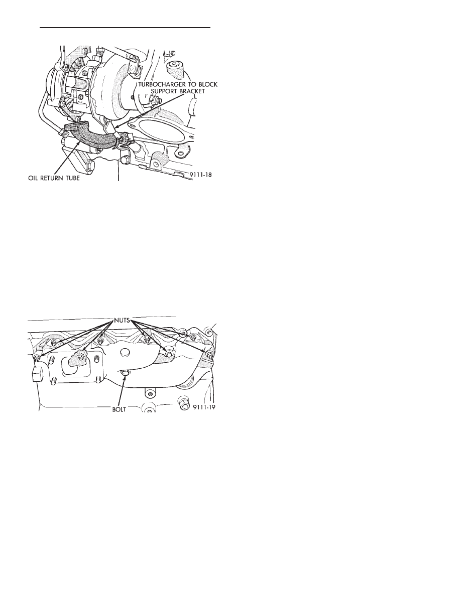
(10) Separate oil drain back tube fitting from tur-
bocharger housing and remove fitting and hose (Fig.
13).
(11) Remove turbocharger to block support bracket
(Fig. 13).
(12) Remove one remaining turbocharger to mani-
fold retaining nut (Fig. 12).
Fig. 11 Coolant Tube Routing
Fig. 12 Turbocharger Attaching Nuts
Fig. 9 Fuel Supply and Return Hose Connections
Fig. 10 Intake Manifold Attaching Bolts.
11 - 12
EXHAUST SYSTEM AND INTAKE MANIFOLD
Ä
(13) Disconnect articulated exhaust pipe joint from
turbocharger housing.
(14) Remove turbocharger coolant inlet line assem-
bly from engine (Fig. 11).
(15) Lift turbocharger off manifold mounting studs
and lower assembly down and out of vehicle.
EXHAUST MANIFOLD
REMOVAL
Remove 9 exhaust manifold retaining fasteners and
remove exhaust manifold (Fig. 14).
CLEANING AND INSPECTION
(1) Discard gasket and clean all gasket surfaces of
manifolds and cylinder head.
(2) Test manifold gasket surfaces for flatness with
straight edge. Surface must be flat within 0.15 mm
per 300 mm (.006 in. per foot) of manifold length.
(3) Inspect manifolds for cracks or distortion. Re-
place manifold if necessary.
EXHAUST MANIFOLD
INSTALLATION
(1) Install new manifold gasket. DO NOT APPLY
SEALER.
(2) Set exhaust manifold in place. Tighten retain-
ing nuts and bolt, starting at center and progressing
outward in both directions to 23 N
Im (200 in. lbs.)
torque. Repeat this procedure until all fasteners are
at specified torque (Fig. 14).
TURBOCHARGER
INSTALLATION
(1) Position turbocharger on exhaust manifold. Ap-
ply antiseize compound to threads and install the
lower
(passenger
side)
retaining
nut
(Fig.
12).
Tighten nut to 54 N
Im (40 ft. lbs.) torque.
(2) Apply thread sealant to lower (inlet) coolant
line fitting and install fitting into turbocharger hous-
ing (Fig. 11).
(3) Install lower coolant line assembly to engine
(Fig. 11).
(4) Install oil drain back tube and fitting (with
new gasket) to turbocharger housing (Fig. 13).
(5) Install turbocharger to block support bracket
and install screws finger tight (Fig. 13). Tighten
block screw FIRST to 54 N
Im (40 ft. lbs.) torque,
then tighten screw to turbocharger housing to 27
N
Im (20 ft. lbs.) torque.
(6) Reposition exhaust pipe. Tighten articulated
joint shoulder bolts to 28 N
Im (250 in. lbs.) torque.
(7) See Suspension, Group 2, and install right
driveshaft and wheel and tire assembly. Install air
deflector on crossmember.
(8)
From Above: Install three turbocharger to
manifold retaining nuts. Tighten to 54 N
Im (40 ft.
lbs.) torque (Fig. 12).
(9) Reconnect Heated Oxygen sensor electrical con-
nection and vacuum lines.
(10) Attach oil feed line to turbocharger bearing
housing. Tighten fitting to 14 N
Im (125 in. lbs.)
torque (Fig. 12).
(11) Install coolant line and tighten fittings to 41
N
Im (30 ft. lbs.) torque (Fig. 11).
(12) Install air cleaner support (Fig. 1).
(13) Align front engine mount in crossmember
bracket. Install through bolt and tighten to 54 N
Im
(40 ft. lbs.) torque.
(14) Install air cleaner assembly (Fig. 1).
(15) Fill cooling system. Refer to Cooling System,
Group 7 for procedure.
INTAKE/EXHAUST MANIFOLD SERVICE—3.0L
ENGINE
The intake system has a large air intake plenum of
aluminum alloy and a cross type intake manifold
(Fig. 2).
Fig. 13 Oil Return Tube and Support Bracket
Fig. 14 Exhaust Manifold—Turbo III Engine
Ä
EXHAUST SYSTEM AND INTAKE MANIFOLD
11 - 13
Нет комментариевНе стесняйтесь поделиться с нами вашим ценным мнением.
Текст