Chrysler Le Baron, Dodge Dynasty, Plymouth Acclaim. Manual — part 218
HYDRAULIC SYSTEM CONTROL VALVES
INDEX
page
page
ABS Brake Proportioning Valve Operation
. . . . . . 27
General Information
. . . . . . . . . . . . . . . . . . . . . . . 26
Hydraulic System Service Procedures
. . . . . . . . . 27
Non-ABS Proportioning Unit Operation
. . . . . . . . 26
Pressure Differential Warning Light Switch
. . . . . . 26
Testing ABS Proportioning Valves
. . . . . . . . . . . . 29
GENERAL INFORMATION
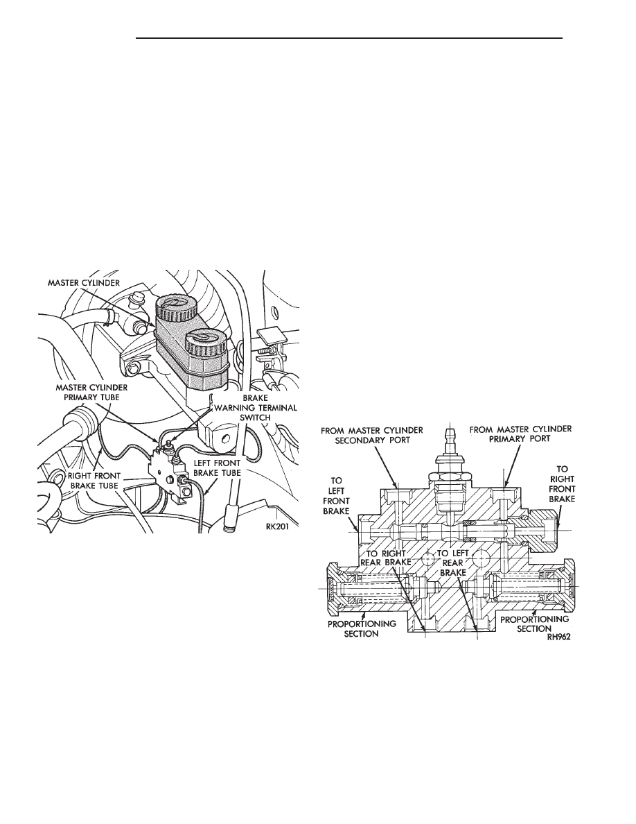
Most models not equipped with an Anti-Lock brak-
ing system have a combination hydraulic system con-
trol valve in the brake hydraulic system (Fig. 1). The
valve is attached to the frame rail below the master
cylinder.
The control valve assembly combines a warning
switch with a dual proportioning valve (Fig. 2)
Proportioning valves balance front to rear braking
by controlling at a given ratio, the increase in rear
system hydraulic pressure above a preset level. Un-
der light pedal application, the valve allows full hy-
draulic pressure to the rear brakes.
There is only one valve assembly in each vehicle,
see Valve Application Chart. During any service pro-
cedures identify valve assemblies by part number as
well as split point (PSI) and slope.
PRESSURE DIFFERENTIAL WARNING LIGHT
SWITCH
The hydraulic brake system, on non-ABS vehicles,
is split diagonally. The left front and right rear
brakes are part of one system. And the right front
and left rear are part of another. Both systems are
routed through, but hydraulically separated by a Pres-
sure Differential Switch. The function of the Pressure
Differential Switch is to alert the driver of a malfunc-
tion in the brake system.
If hydraulic pressure is lost in one system, the
warning light switch will activate a red light on the
instrument panel, when the brake pedal is depressed.
At this point the brakes require service. However, since
the brake systems are split diagonally the vehicle will
retain 50% of its stopping capability in the event of a
failure in either half.
The warning light switch is the latching type. It
will automatically center itself after the repair is
made and the brake pedal is depressed.
The instrument panel bulb can be checked each time
the ignition switch is turned to the start position or the
parking brake is set.
NON-ABS PROPORTIONING UNIT OPERATION
The proportioning valve section operates by trans-
mitting full input pressure to the rear brakes up to a
certain point. This is called the split point. Beyond this
point it reduces the amount of pressure increase to the
rear brakes according to a certain ratio.
On light pedal applications equal brake pressure will
be transmitted to the front and rear brakes. On heavier
pedal
applications
the
pressure
transmitted
Fig. 1 Brake Combination Valve And Warning
Switch Location
Fig. 2 Switch and Valve Assembly
5 - 26
BRAKES
Ä
to the rear will be lower than the front brakes. This will
prevent premature rear wheel lock-up and skid. If
hydraulic pressure is lost in one half of the diagonally
split system, the operation of the proportioning valve
in the remaining half is not effected.
ABS BRAKE PROPORTIONING VALVE OPERATION
On vehicles using the ABS braking system, screw in
proportioning valves are used in place of the conven-
tional differential pressure/proportioning valve.
Each rear brake circuit has its own screw-in propor-
tioning valve which is attached to the rear brake outlet
ports of the hydraulic assembly. These valves limit
brake pressure to the rear brakes after a certain
pressure is reached. This improves front to rear brake
balance during normal braking.
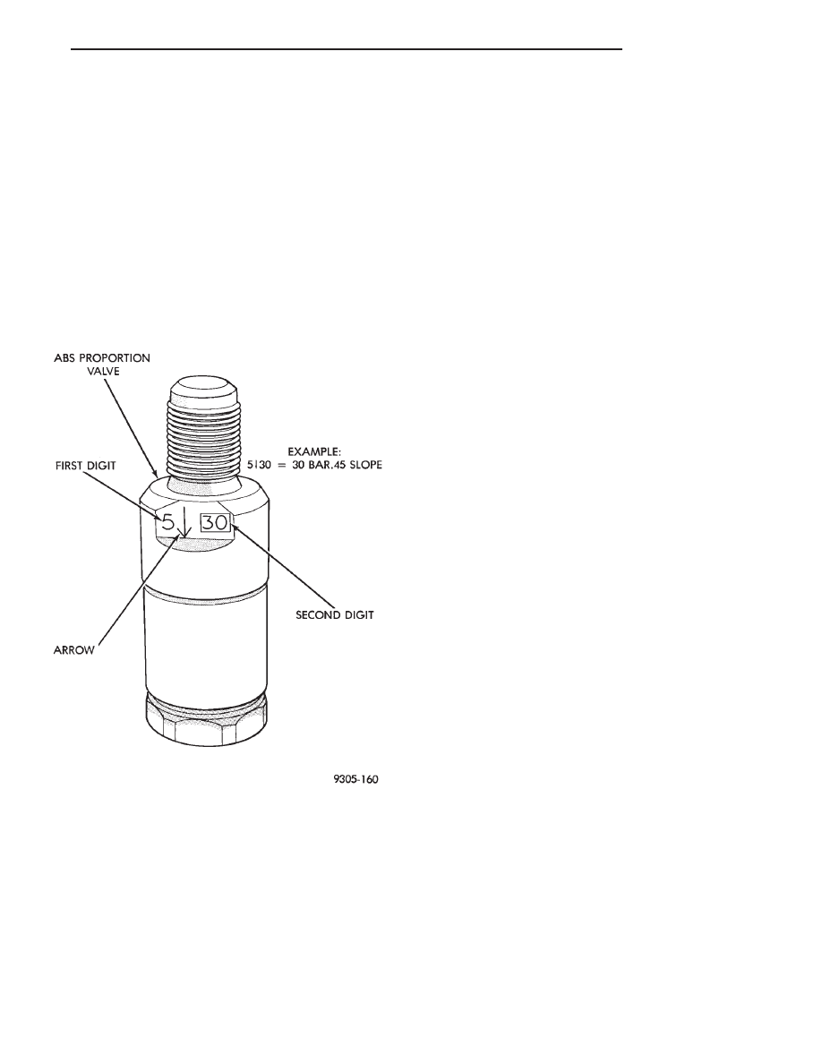
Screw in proportioning valves can be identified by
the numbers stamped on the body of the valve. The
first digit represents the slope, the second digit repre-
sents the split (cut-in) point, and the arrow represents
the flow direction of the valve. Be sure that the
numbers listed on the replacement valve are the
same as on the valve that is being removed. See
(Fig. 3) for detail of the valve identification.
HYDRAULIC SYSTEM SERVICE PROCEDURES
BRAKE WARNING SYSTEM
CHECKING BRAKE WARNING SWITCH UNIT
The Red Brake Warning light will come on when
the parking brake is applied with the ignition key
turned ON. The same light will also illuminate
should one of the two service brake hydraulic sys-
tems fail.
CAUTION:Make sure air does not enter the hydrau-
lic system during this test procedure. See bleeding
without a pressure bleeder at the beginning of this
section for master cylinder fluid level checking pro-
cedures.
To test the service brake warning system lamp.
Raise the vehicle on a hoist and open a wheel cylin-
der bleeder while a helper depresses the brake pedal
and observes the warning light.
If the light fails to light, inspect for a burned out
bulb, disconnected socket, or a broken or discon-
nected wire at the switch. If the bulb is not burned
out and the wire continuity is uninterrupted. Check
the service brake warning switch operation with a
test lamp between the switch terminal and a known
good ground. Be sure to fill master cylinder and
bleed brake system after correction has been made, if
necessary.
PROPORTIONING VALVES
TESTING PROPORTIONING VALVE UNIT
If premature rear wheel skid occurs on hard brake
application, it could be an indication that a malfunc-
tion has occurred with the proportioning valve unit.
The proportioning valve is designed with two sep-
arate systems. One half controls the right rear
brake, and the other half controls the left rear brake.
Therefore, a road test to determine which rear brake
slides first is essential.
RIGHT REAR WHEEL SLIDES FIRST
To test the proportioning valve when the right rear
wheel slides first, leave the front brakes connected to
the valve, proceed as follows:
(1) Install one gauge and (TEE) of set C-4007-A
between the brake line from the master cylinder sec-
ondary port and the brake valve assembly.
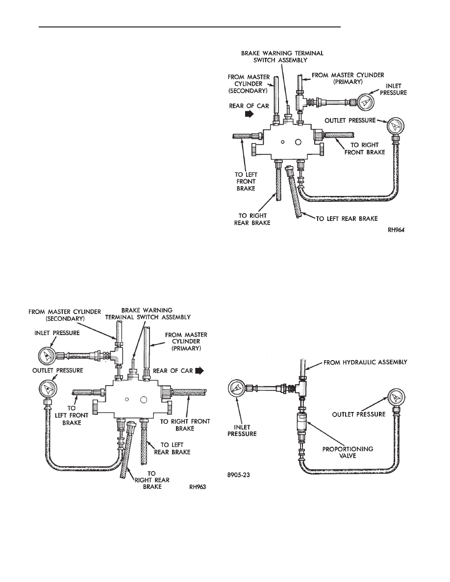
(2) Install the second gauge of set C-4007-A to the
right rear brake outlet port (Fig. 4). Using an
adapter tube, made from a short piece of brake tube
and (2) 3/8 x 24 tube nuts. Connect the hose to the
valve. Bleed the hose and gauge.
(3) Have a helper exert pressure on the brake
pedal (holding pressure) to get a reading on the valve
inlet gauge and check the reading on the outlet
Fig. 3 ABS PROPORTIONING VALVE IDENTIFICA-
TION
Ä
BRAKES
5 - 27
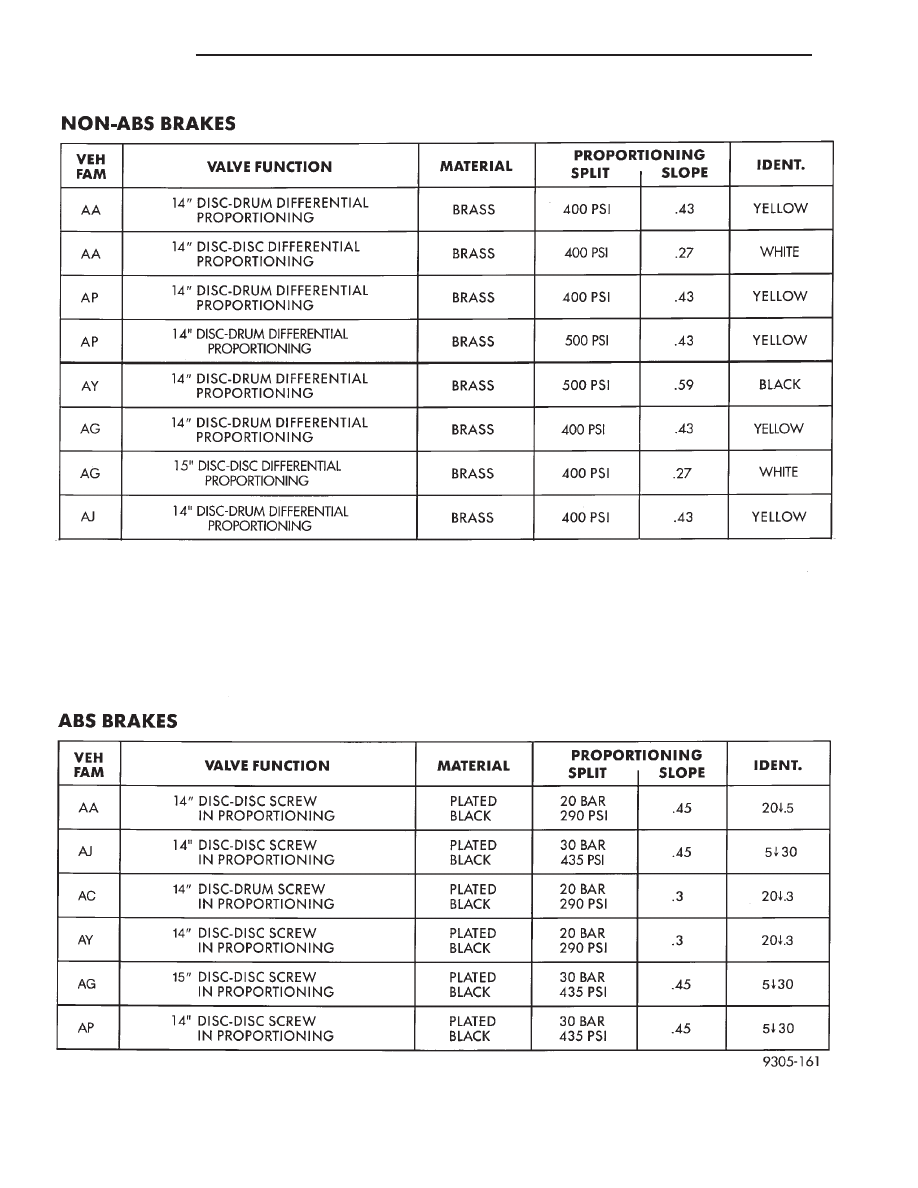
PROPORTIONING VALVE APPLICATIONS
5 - 28
BRAKES
Ä
gauge. If the inlet and outlet pressures do not agree
with the values on the following chart, replace the
valve.
LEFT REAR WHEEL SLIDES FIRST
To test the proportioning valve when the left rear
wheel slides first, leave the front brakes connected to
the valve, proceed as follows:
(1) Install one gauge and (TEE) of set C-4007-A
between brake line from the master cylinder primary
port and the brake valve assembly.
(2) Install the second gauge of set C-4007-A to the
left rear brake outlet port (Fig. 5). An adapter tube,
made up from a 7/16 x 24 tube nut, a short piece of
brake tube and 3/8 x 24 tube nut. Will be required to
connect the hose to the valve. Bleed the gauge and
hose.
(3) Have a helper exert pressure on the brake
pedal. Hold pressure steady to get a reading on the
valve inlet gauge and check the reading on the outlet
gauge. If the inlet and outlet pressures do not agree
with the values on the following chart, replace the
valve.
TESTING ABS PROPORTIONING VALVES
All ABS components use an ISO type tubing flare.
Use the correct adapters with ISO type tubing flares
when installing gauges to test ABS proportioning
valves.
(1) Install one gauge and (TEE) between the hy-
draulic assembly and the male end (Inlet) of the
valve.
(2) Install the second gauge at the female end
(Outlet) of the valve (Fig. 6).
(3) Have a helper exert pressure on the brake
pedal (holding pressure) to get a reading on the valve
inlet gauge.
(4) Check the reading on the outlet gauge. If the
inlet and outlet pressures do not agree with the fol-
lowing chart, replace the valve. See (Fig. 3) for pro-
portioning valve identification.
Fig. 4 Tube Connection for Right Rear Skidding
Fig. 5 Tube Connection for Left Rear Skidding
Fig. 6 Tube Connections for ABS
Ä
BRAKES
5 - 29
Нет комментариевНе стесняйтесь поделиться с нами вашим ценным мнением.
Текст