Chrysler Le Baron, Dodge Dynasty, Plymouth Acclaim. Manual — part 219
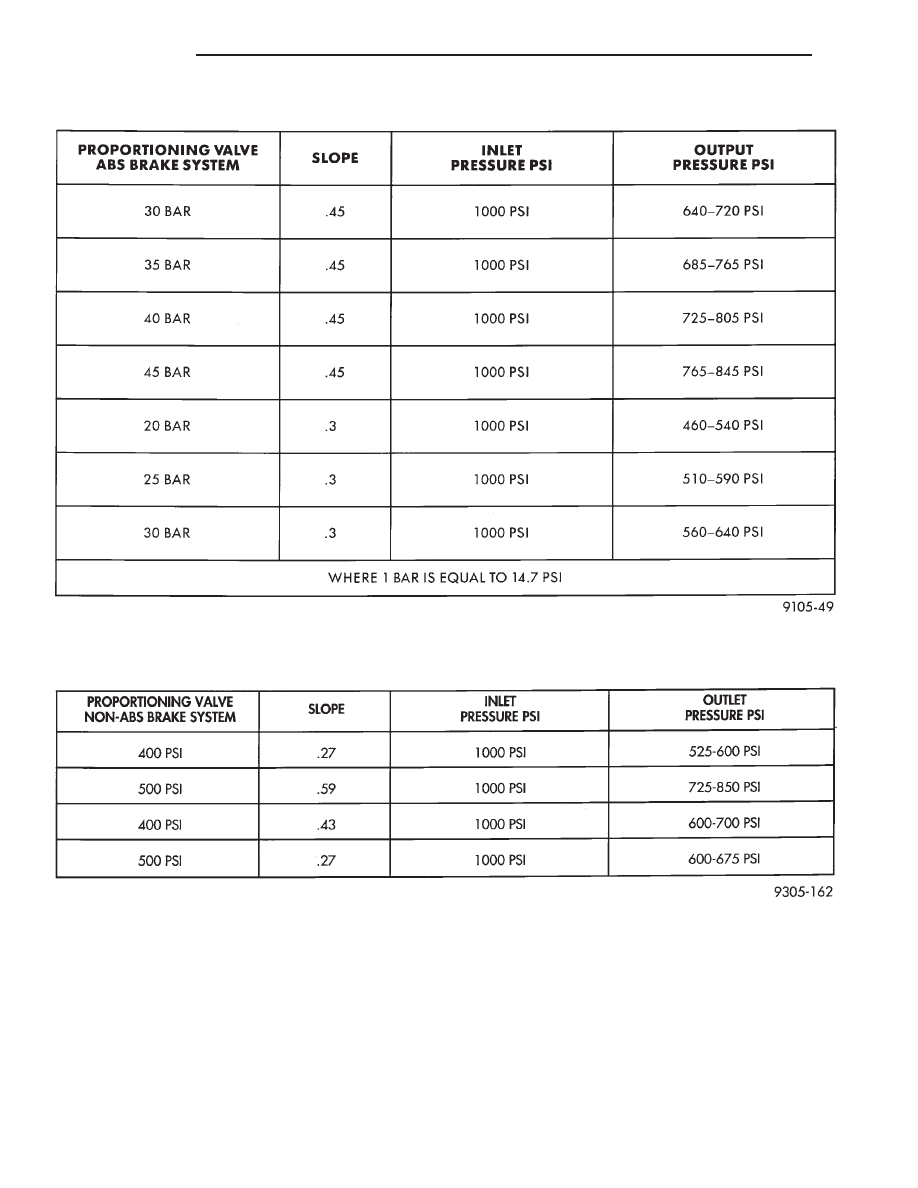
PROPORTIONING VALVE PRESSURES ABS-BRAKES
PROPORTIONING VALVE PRESSURES NON-ABS BRAKES
5 - 30
BRAKES
Ä
FRONT DISC BRAKES
INDEX
page
page
General Information
. . . . . . . . . . . . . . . . . . . . . . . 31
Service Precautions
. . . . . . . . . . . . . . . . . . . . . . . 34
Shoe and Lining Wear
. . . . . . . . . . . . . . . . . . . . 33
GENERAL INFORMATION
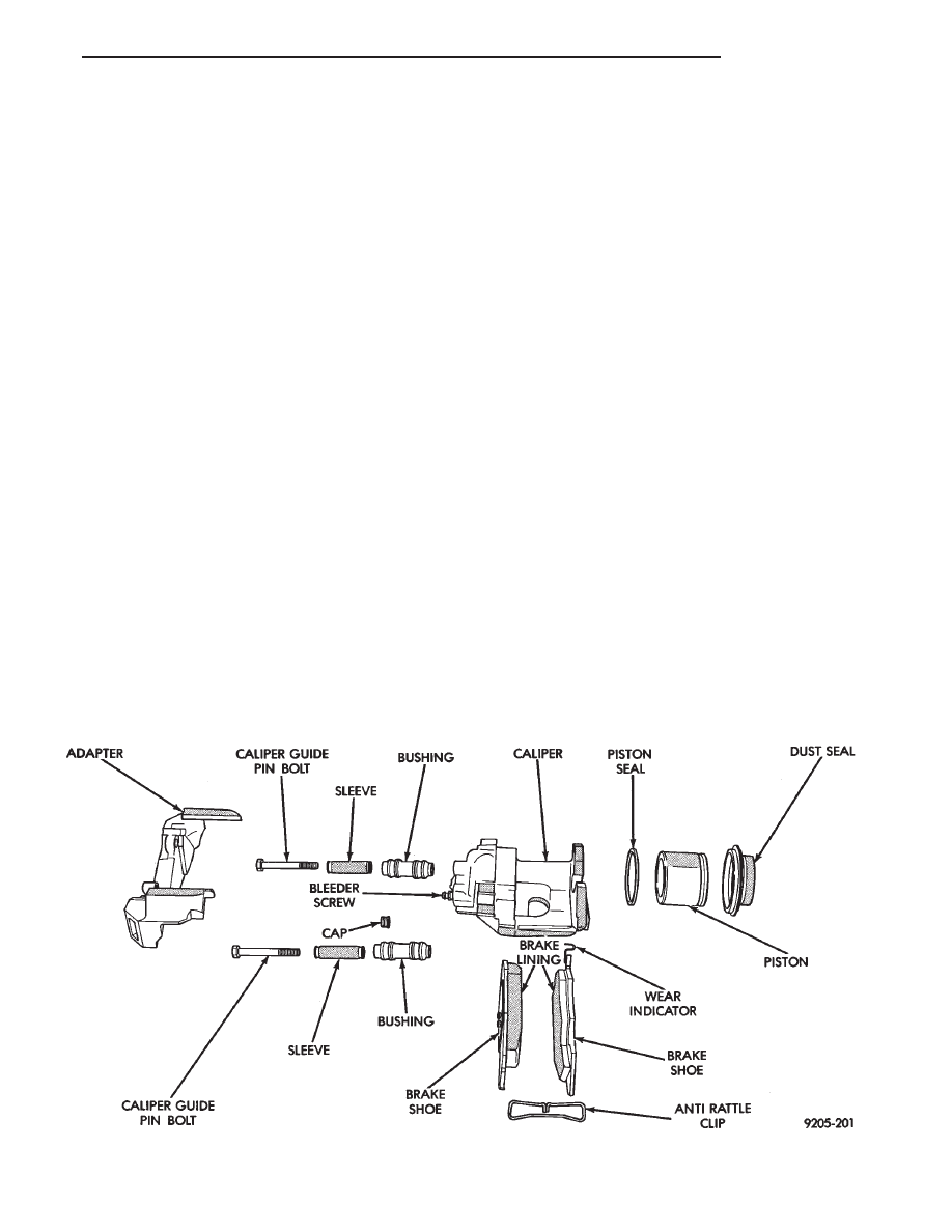
The single piston, floating caliper disc brake as-
sembly (Fig. 1 and 2) consists of:
• The driving hub
• Braking disc (rotor)
• Caliper assembly
• Shoes and linings
• Adapter for mounting the caliper assembly to the
steering knuckle
WARNING: THE PISTONS THAT ARE USED
IN THE 2 DIFFERENT CALIPER ASSEMBLIES
ARE UNIQUE TO THE CALIPER THEY ARE
USED IN. THE DIMENSIONS OF THESE PIS-
TONS
ARE
DIFFERENT,
DO
NOT
INTER-
CHANGE
THE
CALIPER
PISTONS.
IMPROPER
USE
COULD
CAUSE
A
COM-
PLETE FAILURE OF THE BRAKE SYSTEM.
The double pin Kelsey-Hayes Family Caliper, is
mounted to the adapter using bushings, sleeves and
2 through bolts threaded into the adapter (Fig. 3 and
5). The adapter is then mounted to the steering
knuckle using 2 attaching bolts.
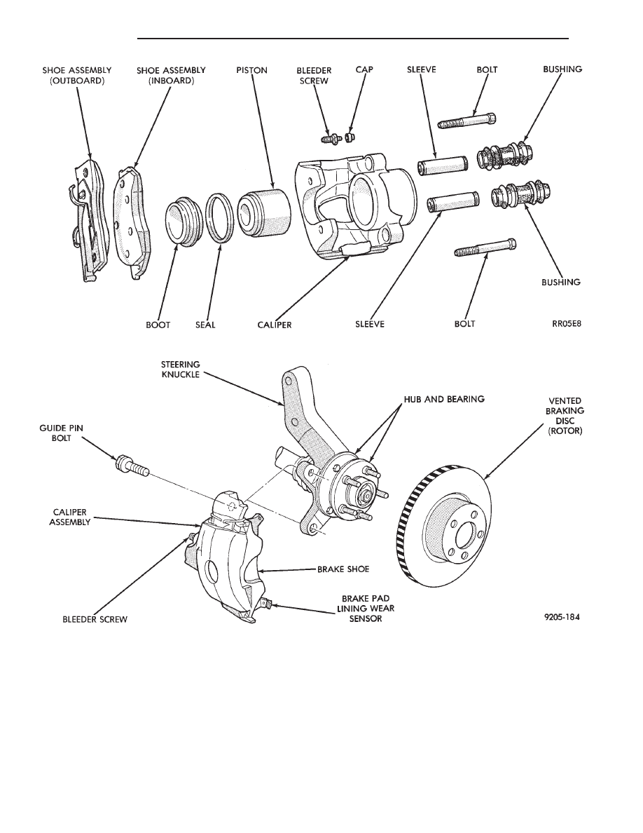
The double pin Kelsey-Hayes Non-Family Caliper,
is mounted directly to the steering knuckle of the ve-
hicle using bushings, sleeves and 2 through bolts
(Fig. 4). The adapter is not used on the vehicles
equipped with the Non-Family caliper assembly.
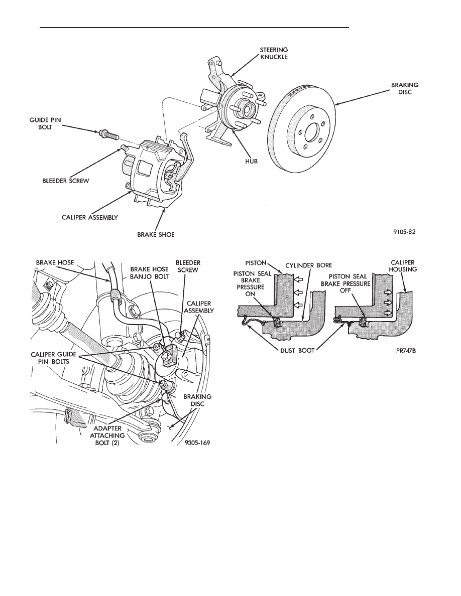
Two machined abutments on the caliper mounting
adapter or steering knuckle, (Fig. 3 and 4) position
the caliper fore and aft. The guide pin bolts, sleeves
and bushings control the float, side to side movement
of the caliper. The piston seal, is designed to pull the
piston back into the bore of the caliper when the
brake pedal is released. This maintains proper brake
shoe to rotor clearance (Fig. 6).
Vehicles equipped with Kelsey-Hayes double pin
family calipers, have 1 anti-rattle clip attached to
the top of the adapter (Fig. 1).
All of the braking force is taken up directly by the
adapter or the steering knuckle depending on the
type of caliper assembly the vehicle is equipped with.
The caliper is a one piece casting with the inboard
side containing a single piston cylinder bore.
The front disc brake caliper phenolic piston is 2 dif-
ferent sizes depending on the vehicle that the caliper
assembly is used on. The AC, AG & AY body use a
60 mm piston, and the AA, AP, AG & AJ body use a
54 mm piston.
Fig. 1 Front Disc Brake Assembly (Family Caliper Typical)
Ä
BRAKES
5 - 31
A square cut rubber piston seal is located in a ma-
chined groove in the cylinder bore. This provides a
hydraulic seal between the piston and the cylinder
wall (Fig. 6).
A molded rubber dust boot is installed in a groove
of the caliper assembly piston bore. This prevents
contamination in the bore area of the caliper assem-
bly.
The boot mounts in the cylinder bore opening and
in a groove in the piston (Fig. 6). This prevents con-
tamination in the bore area.
As lining wears, master cylinder reservoir brake
fluid level will go down. If brake fluid has been
added to the reservoir, reservoir overflow may occur
when the piston is pushed back into the new lining
position. Overflowing can be avoided in this case by
removing a small amount of fluid from the master
cylinder reservoir.
All Vehicles, are equipped with an audible wear
sensor on the outboard pad of the front disc brake as-
Fig. 2 Front Disc Brake Assembly (Non-Family Caliper Typical)
Fig. 3 Disc Brake Caliper Mounting (Family Caliper)
5 - 32
BRAKES
Ä
semblies. This sensor when emitting a sound signals
that brake lining may need inspection and/or re-
placement.
SHOE AND LINING WEAR
If a visual inspection does not adequately deter-
mine the condition of the lining, a physical check
will be necessary. To check the amount of lining
wear, remove the wheel and tire assemblies, and the
calipers.
Remove the shoe and lining assemblies. (See Brake
Shoe Removal paragraph).
Combined shoe and lining thickness should be
measured at the thinnest part of the assembly.
When a shoe and lining assembly is worn to a
thickness of approximately 7.95 mm (5/16 inch) it
should be replaced.
Replace both shoe assemblies (inboard and out-
board) on the front wheels. It is necessary that both
front wheel sets be replaced whenever shoe assem-
blies on either side are replaced.
If a shoe assembly does not require replacement.
Reinstall, the shoe assemblies making sure each shoe
assembly is returned to the original position. (See
Brake Shoe Installation).
Fig. 4 Disc Brake Caliper Mounting (Non-Family Caliper)
Fig. 5 Disc Brake Caliper Mounting (Typical)
Fig. 6 Piston Seal Function for Automatic
Adjustment
Ä
BRAKES
5 - 33
Нет комментариевНе стесняйтесь поделиться с нами вашим ценным мнением.
Текст