Chrysler Le Baron, Dodge Dynasty, Plymouth Acclaim. Manual — part 171

CONVER
TIBLE
TOP
DIMENSIONS
23 - 94
AJ/27-BODY
Ä
HYDRAULIC SYSTEMS
The power convertible top hydraulic system con-
sists of;
• Two hydraulic cylinders
• Hydraulic lines
• Electric hydraulic pump and reservoir
• Dual relays
HYDRAULIC SYSTEM TESTS
The convertible top will raise slowly or make ab-
normal noise if the hydraulic fluid level is low.
(1) Remove sling well and floor cover.
(2) With the top up and latched, remove the reser-
voir fill plug.
(3) Visually inspect fluid level. If low, inspect for
leak in hydraulic system.
(4) Repair or replace components, as necessary.
(5) Fill reservoir with Dexron
t II, Type A, auto-
matic transmission fluid to the bottom of the fill
hole.
(6) Replace fill plug and lower top.
(7) Raise top and verify fluid level.
(8) Install sling well and floor cover.
HYDRAULIC PUMP ASSEMBLY
HYDRAULIC PUMP REMOVAL (FIG. 13)
(1) Disconnect battery negative cable.
(2) Remove sling well and floor cover from behind
rear seat.
(3) Disconnect pump wire connector and ground
connection.
(4) Disconnect hydraulic lines from pump.
(5) Remove motor pump assembly from vehicle.
The rubber mounts are pressed and locked into the
mounting bracket. Pull up motor assembly to re-
move.
HYDRAULIC PUMP INSTALLATION
Reverse the preceding operation
HYDRAULIC CYLINDER
HYDRAULIC CYLINDER REMOVAL
(1) Disconnect battery negative cable.
(2) Remove interior trim as necessary to gain ac-
cess to hydraulic cylinders.
(3) Remove cylinder mounting bracket and nut.
(4) Remove pivot bolt holding cylinder shaft to top
linkage.
(5) Disconnect hydraulic lines from the cylinder.
(6) Remove cylinder from vehicle.
HYDRAULIC CYLINDER INSTALLATION
Reverse the preceding operation, and verify each
hydraulic seal is in place when connecting the line to
the cylinder. Replace seal if damaged.
HYDRAULIC PUMP LINE SEALS
HYDRAULIC PUMP LINE SEALS REMOVAL
(1) Disconnect battery negative cable.
(2) Disconnect hydraulic lines from pump and re-
move seals.
HYDRAULIC PUMP LINE SEALS
INSTALLATION
Reverse the preceding operation.
HYDRAULIC CYLINDER LINE SEALS
REMOVAL
(1) Remove hydraulic cylinder to gain access to hy-
draulic line connections.
(2) Disconnect hydraulic lines from cylinder and
remove seals.
INSTALLATION
Reverse the preceding operation.
Ä
AJ/27-BODY
23 - 95

Fig. 13 Hydraulic System
23 - 96
AJ/27-BODY
Ä
AP-VEHICLE BODY COMPONENT SERVICE
INDEX
page
page
A-Pillar and Roof Rail Mouldings
B-Pillar Trim Panel—AP-44 Body
Body Side Moulding and Applique
Cowl Panel Trim and Scuff Plates
. . . . . . . . . . . . . . . 107
. . . . . . . . . . . . . . . . . . . . . . . . . . . 113
. . . . . . . . . . . . . . . . . . . . 113
. . . . . . . . . . . . . . . . . . . . 100
Front Door Belt Moulding and Weatherstrip
. . . . . . . . . . . . . . . . . . . . . . . . 101
Front Door Glass Channel and Run
. . . . . . . . . . . . . . . . . . . . . . . . . . 103
Front Door Glass Run Lower Channels
. . . . . . . . . . . . . . . . . . . . . . . . 101
. . . . . . . . . . . . . . . 101
Front Door Trim Panel—AP-24/44 Body
. . . . . . . . . . . . . . . . . . 100
Front Door Window Regulator/Manual
Front Door Window Regulator/Power
. . . . . . . . . . . . . . . . . . 99
Front Power Door Lock Actuator
. . . . . . . . . . . . . . 110
. . . . . . . . . . . . . . 110
. . . . . . . . . . . . . . . . . . . . . . . . . . . . 111
. . . . . . . . . . . . . . . . . . . . . . . . . . . . . . . . . . 97
. . . . . . . . . . . . . . . . . . . . . . 97
. . . . . . . . . . . . . . . . . . . . . . . . . . . . 114
. . . . . . . . . . . . . . . . . . . . . . . . 97
. . . . . . . . . . . . . . 98
. . . . . . . . . . . . . . . . . . . 116
Lift Gate Remote Release Cable
Lower Quarter Trim Panel—AP-44 Body
Outside Front Door Latch Release Handle
Outside Rear Door Latch Release Handle
. . . . . . . . . . . . . . . . . . . . . . . 113
. . . . . . . . . . . . . . . . 108
. . . . . . . . . . . . . . . . . . . 108
. . . . . . . . . . . . . . . . . . . . 104
Rear Door Belt Moulding and Weatherstrip
. . . . . . . . . . . . . . . . . . . . . . . . 106
Rear Door Glass Run Weatherstrip
. . . . . . . . . . . . . . . . . . . . . . . . 105
Rear Door Silencer and Water Shield
. . . . . . . . . . . . . . . . 107
. . . . . . . . . . . . . . . . . . . . 104
Rear Door Window Regulator/Manual
Rear Door Window Regulator/Power
. . . . . . . . . . . . . . . . . . . . . . . . . 111
. . . . . . . . . . . . . . . . . . . . . . . . . . . . 112
. . . . . . . . . . . . . . . . . . . . . . 115
. . . . . . . . . . . . . . . . . . . 114
. . . . . . . . . . . . . . . . . . . . 115
. . . . . . . . . . . . . . . . . . . 114
Upper Quarter Trim Panel—AP-44 Body
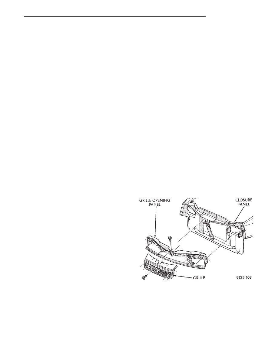
GRILLE
REMOVAL (FIG. 1)
(1) Raise hood to the up position.
(2) Remove screws holding grille to grille opening
panel.
(3) Separate grille from vehicle.
INSTALLATION
Reverse the preceding operation.
GRILLE OPENING PANEL
REMOVAL (FIG. 1)
(1) Remove grille from grille opening panel.
(2) Remove headlamp assemblies. Refer to Group
8L. Lamps for proper procedures.
(3) Remove bolts holding grille opening panel to
closure panel brackets.
(4) Remove bolt holding grille opening panel to
brace in front of radiator.
(5) Separate grille opening panel from vehicle.
INSTALLATION
Reverse the preceding operation.
HOOD AND HINGES
HOOD REMOVAL (FIG. 2)
(1) Raise hood to full up position.
(2) Disconnect the under hood lamp wire connec-
tor.
(3) Mark all bolt and hinge attachment locations
with a grease pencil or other suitable device to pro-
vide reference marks for installation. When install-
Fig. 1 Grille and Grille Opening Panel
Ä
AP-BODY
23 - 97
Нет комментариевНе стесняйтесь поделиться с нами вашим ценным мнением.
Текст