Chrysler Le Baron, Dodge Dynasty, Plymouth Acclaim. Manual — part 62
S/C Vacuum Solenoid
A/C Clutch Relay
EGR Solenoid
Auto Shutdown Relay
Radiator Fan Relay
Purge Solenoid
Malfunction Indicator Lamp (Check Engine Lamp)
STATE DISPLAY SENSORS
Connect the DRBII scan tool to the vehicle and ac-
cess the State Display screen. Then access Sensor
Display. The following is a list of the engine control
system functions accessible through the Sensor Dis-
play screen.
Oxygen Sensor Signal
Engine Coolant Temperature
Engine Coolant Temp Sensor
Throttle Position
Minimum Throttle
Battery Voltage
MAP Sensor Reading
Idle Air Control Motor Position
Adaptive Fuel Factor
Barometric Pressure
Min Airflow Idle Spd (speed)
Engine Speed
DIS Sensor Status
Fault #1 Key-On Info
Module Spark Advance
Speed Control Target
Fault #2 Key-on Info
Fault #3 Key-on Info
Speed Control Status
Speed Control Switch Voltage
Charging System Goal
Theft Alarm Status
Map Sensor Voltage
Vehicle Speed
Oxygen Sensor State
MAP Gauge Reading
Throttle Opening (percentage)
Total Spark Advance
CIRCUIT ACTUATION TEST MODE
The circuit actuation test mode checks for proper
operation of output circuits or devices which the pow-
ertrain control module (PCM) cannot internally rec-
ognize. The PCM can attempt to activate these
outputs and allow an observer to verify proper oper-
ation. Most of the tests provide an audible or visual
indication of device operation (click of relay contacts,
spray fuel, etc.). Except for intermittent conditions, if
a device functions properly during testing, assume
the device, its associated wiring, and driver circuit
working correctly.
OBTAINING CIRCUIT ACTUATION TEST
Connect the DRBII scan tool to the vehicle and ac-
cess the Actuators screen. The following is a list of
the
engine
control
system
functions
accessible
through Actuators screens.
Stop All Tests
Ignition Coil #1
Ignition Coil #2
Ignition Coil #3
Fuel Injector #1
Fuel Injector #2
Fuel Injector #3
Fuel Injector #4
Fuel Injector #5
Fuel Injector #6
Idle Air Control Motor Open/Close
Radiator Fan Relay
A/C Clutch Relay
Auto Shutdown Relay
EVAP Purge Solenoid
S/C Servo Solenoids
Generator Field
EGR Solenoid
All Solenoids/Relays
ASD Fuel System Test
Speed Control Vacuum Solenoid
Speed Control Vent Solenoid
THROTTLE BODY MINIMUM AIR FLOW CHECK
PROCEDURE
(1) Warm engine in Park or Neutral until the cool-
ing fan has cycled on and off at least once.
(2) Ensure that all accessories are off.
(3) Shut off engine.
(4) Disconnect the PCV valve hose from the intake
manifold nipple.
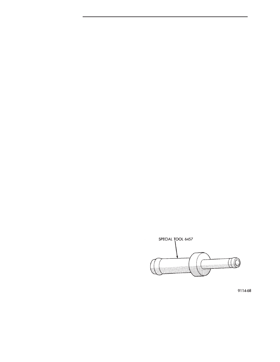
(5) Attach Air Metering Fitting #6457 (0.125 in.
orifice) to the intake manifold PCV nipple (Fig. 2).
(6) Disconnect the 3/16 inch idle purge line from
the throttle body nipple. Cap the 3/16 inch nipple.
(7) Connect DRBII scan tool to vehicle.
(8) Restart the engine. Allow engine to idle for at
least one minute.
(9) Using the DRBII scan tool, access Min. Airflow
Idle Spd.
Fig. 2 Air Metering Fitting #6457
14 - 166
FUEL SYSTEMS
Ä
(10) The following will then occur:
• Idle air control motor will fully close.
• Idle spark advance will become fixed.
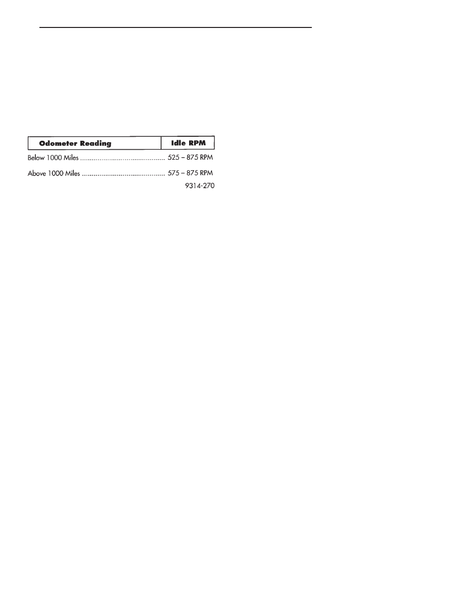
• Engine RPM will be displayed on DRBII scan tool.
(11) If idle RPM is within the range shown in the
Idle Specification chart, throttle body minimum air-
flow is set correctly.
(12) If idle RPM is not within specifications, shut off
the engine and clean the throttle body as follows:
(a) Remove the throttle body from engine.
WARNING: CLEAN THROTTLE BODY IN A WELL
VENTILATED AREA. WEAR RUBBER OF BUTYL
GLOVES, DO NOT LET MOPAR PARTS CLEANER
COME IN CONTACT WITH EYES OR SKIN. AVOID
INGESTING THE CLEANER. WASH THOROUGHLY
AFTER USING CLEANER.
(b) While holding the throttle open, spray the
entire throttle body bore and the manifold side of the
throttle plate with Mopar Parts Cleaner. Only use
Mopar Parts Cleaner to clean the throttle body.
(c) Using a soft scuff pad, clean the top and bottom
of throttle body bore and the edges and manifold side
of the throttle blade. The edges of the throttle
blade and portions of the throttle bore that are
closest to the throttle blade when is closed,
must be free of deposits.
(d) Use compressed air to dry the throttle body.
(e) Inspect throttle body for foreign material.
(f) Install throttle body on manifold.
(g) Repeat steps 1 through 14. If the minimum air
flow is still not within specifications, the problem is
caused by the throttle body. Replace the throttle
body.
(13) Shut off engine.
(14) Remove Air Metering Fitting #6457 from the
intake manifold PCV nipple. Reinstall the PCV valve
hose.
(15) Uncap the throttle body idle purge nipple and
connect the idle purge line.
(16) Remove DRBII scan tool.
60-WAY PCM WIRING CONNECTOR
Refer to the PCM wiring connector diagram (Fig. 3)
for wire colors and cavity numbers.
IDLE SPECIFICATIONS
Ä
FUEL SYSTEMS
14 - 167
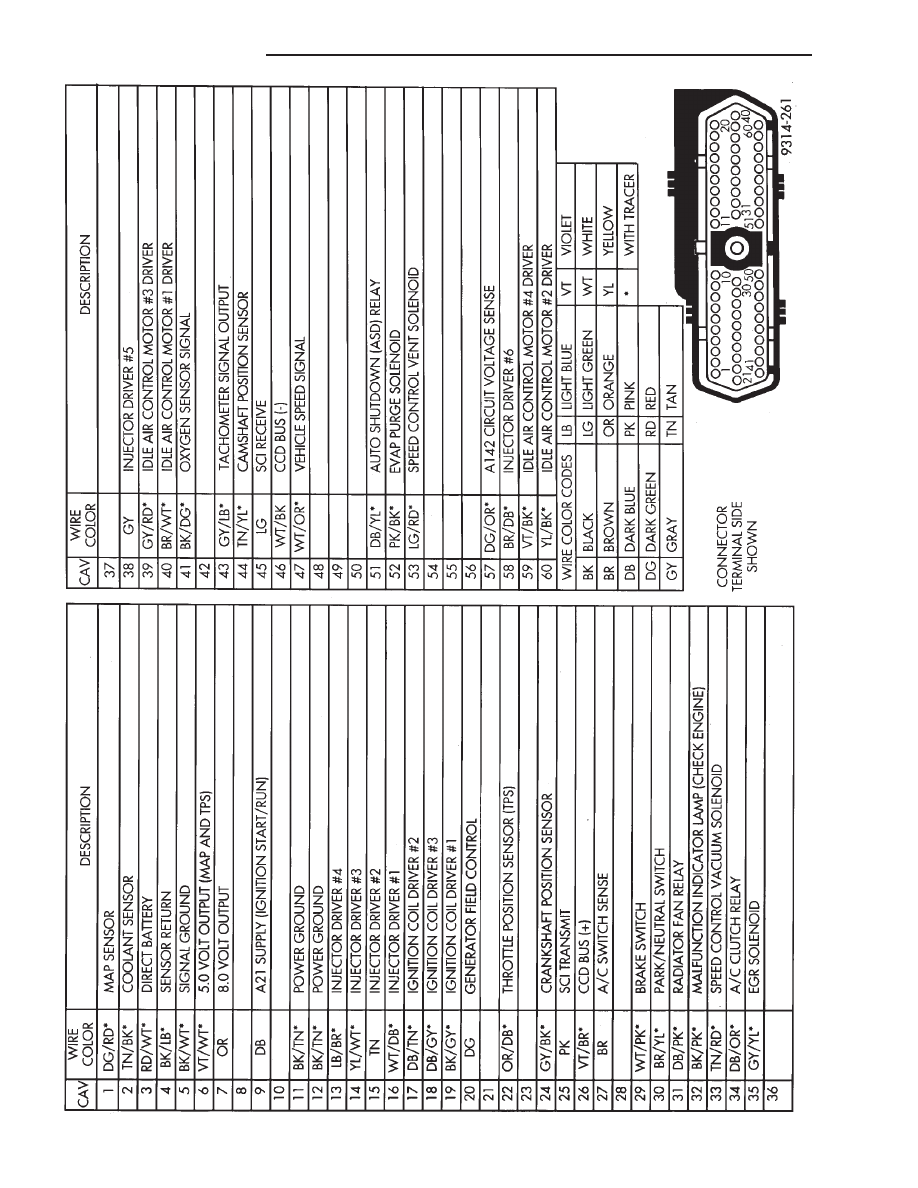
Fig.
3
60-W
ay
PCM
W
iring
Connector
14 - 168
FUEL SYSTEMS
Ä
3.3L AND 3.8L MULTI-PORT FUEL INJECTION—SERVICE PROCEDURES
INDEX
page
page
Camshaft Position Sensor Service
. . . . . . . . . . . 176
Crankshaft Position Sensor
. . . . . . . . . . . . . . . . 176
EVAP Canister Purge Solenoid Service
. . . . . . . 175
Fuel Injector
. . . . . . . . . . . . . . . . . . . . . . . . . . . 174
Fuel Injector Rail Assembly
. . . . . . . . . . . . . . . . 170
Fuel Pressure Regulator
. . . . . . . . . . . . . . . . . . 173
Fuel System Pressure Release Procedure
. . . . . 169
Heated Oxygen Sensor (O
2
Sensor) Service
. . . 177
Idle Air Control Motor
. . . . . . . . . . . . . . . . . . . . 170
Manifold Absolute Pressure (MAP) Sensor
. . . . . 175
PCM Service
. . . . . . . . . . . . . . . . . . . . . . . . . . . 175
Throttle Body
. . . . . . . . . . . . . . . . . . . . . . . . . . . 169
Throttle Body Removal
. . . . . . . . . . . . . . . . . . . 169
Throttle Position Sensor
. . . . . . . . . . . . . . . . . . 169
THROTTLE BODY REMOVAL
(1) Disconnect negative battery cable.
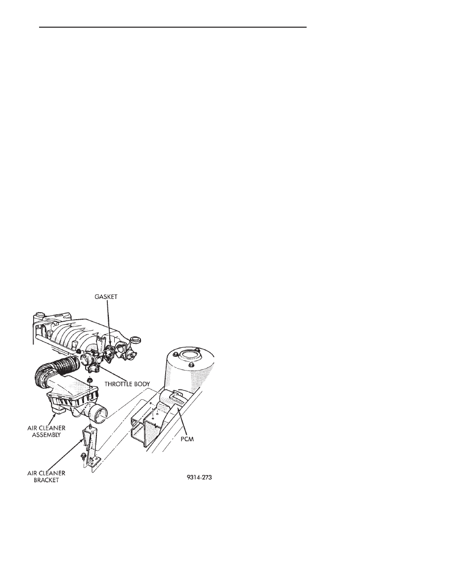
(2) Remove the air cleaner to throttle body hose
clamp. Remove the nut holding the air cleaner as-
sembly to the air cleaner bracket. Remove the air
cleaner (Fig. 1).
(3) Remove throttle and the speed control cables.
(4) Disconnect electrical connectors from the idle
air control motor and throttle position sensor (TPS).
(5) Disconnect vacuum hoses from throttle body.
(6) Remove throttle body to intake manifold at-
taching nuts.
(7) Remove throttle body and gasket.
(8) Reverse the above procedure for installation.
THROTTLE BODY
When servicing throttle body components, always
reassemble components with new O-rings and seals
where applicable (Fig. 2). Never use lubricants on
O-rings or seals, damage may result. If assembly of
component is difficult, use water to aid assembly.
Use care when removing hoses to prevent damage to
hose or hose nipple.
FUEL SYSTEM PRESSURE RELEASE PROCEDURE
WARNING: THE 3.3L AND 3.8L MPI FUEL SYSTEMS
ARE UNDER A CONSTANT PRESSURE OF AP-
PROXIMATELY 330 KPA (48 PSI). RELEASE FUEL
SYSTEM
PRESSURE
BEFORE
SERVICING
THE
FUEL PUMP, FUEL LINES, FUEL FILTER, THROT-
TLE BODY OR FUEL INJECTORS.
(1) Disconnect negative cable from battery.
(2) Remove fuel filler cap.
(3) Remove the protective cap from the fuel pres-
sure test port on the fuel rail (Fig. 3).
(4) Place the open end of fuel pressure release
hose, tool number C-4799-1, into an approved gaso-
line container. Connect the other end of hose
C-4799-1 to the fuel pressure test port. Fuel pressure
will bleed off through the hose into the gasoline con-
tainer. Fuel gauge C-4799-A contains hose C-4799-1.
(5) Continue fuel system service.
THROTTLE POSITION SENSOR
REMOVAL
(1) Disconnect negative cable from battery.
(2) Remove electrical connector from throttle posi-
tion sensor.
(3) Remove
throttle
position
sensor
mounting
screws (Fig. 4).
(4) Lift throttle position sensor off throttle shaft.
INSTALLATION
(1) Install throttle position sensor on throttle shaft.
Install mounting screws. Tighten screw to 2 N
Im (17
in. lbs.) torque.
(2) Connect electrical connector to throttle position
sensor.
(3) Connect negative cable to battery.
Fig. 1 Throttle Body Assembly
Ä
FUEL SYSTEMS
14 - 169
Нет комментариевНе стесняйтесь поделиться с нами вашим ценным мнением.
Текст