Chrysler Le Baron, Dodge Dynasty, Plymouth Acclaim. Manual — part 63
IDLE AIR CONTROL MOTOR
REMOVAL
(1) Disconnect negative cable from battery.
(2) Remove electrical connector from idle air con-
trol motor.
(3) Remove idle air control motor mounting screws
(Fig. 5).
(4) Remove idle air control motor from throttle
body. Ensure the O-ring is removed with the motor.
INSTALLATION
(1) New idle air control motors have a new O-ring
installed on it. If pintle measures more than 1 inch
(25 mm) it must be retracted. Use the DRBII scan
tool Idle Air Control Motor Open/Close Test to re-
tract the pintle (battery must be connected.)
(2) Carefully place idle air control motor into
throttle body.
(3) Install mounting screws. Tighten screws to 2
N
Im (17 in. lbs.) torque.
(4) Connect electrical connector to idle air control
motor.
(5) Connect negative cable to battery.
FUEL INJECTOR RAIL ASSEMBLY
REMOVAL
(1) Perform fuel system pressure release procedure
before servicing or starting repairs. Refer to Fuel
System Pressure Release Procedure in this section.
(2) Disconnect negative cable from battery.
(3) Remove air cleaner and hose assembly (Fig. 1).
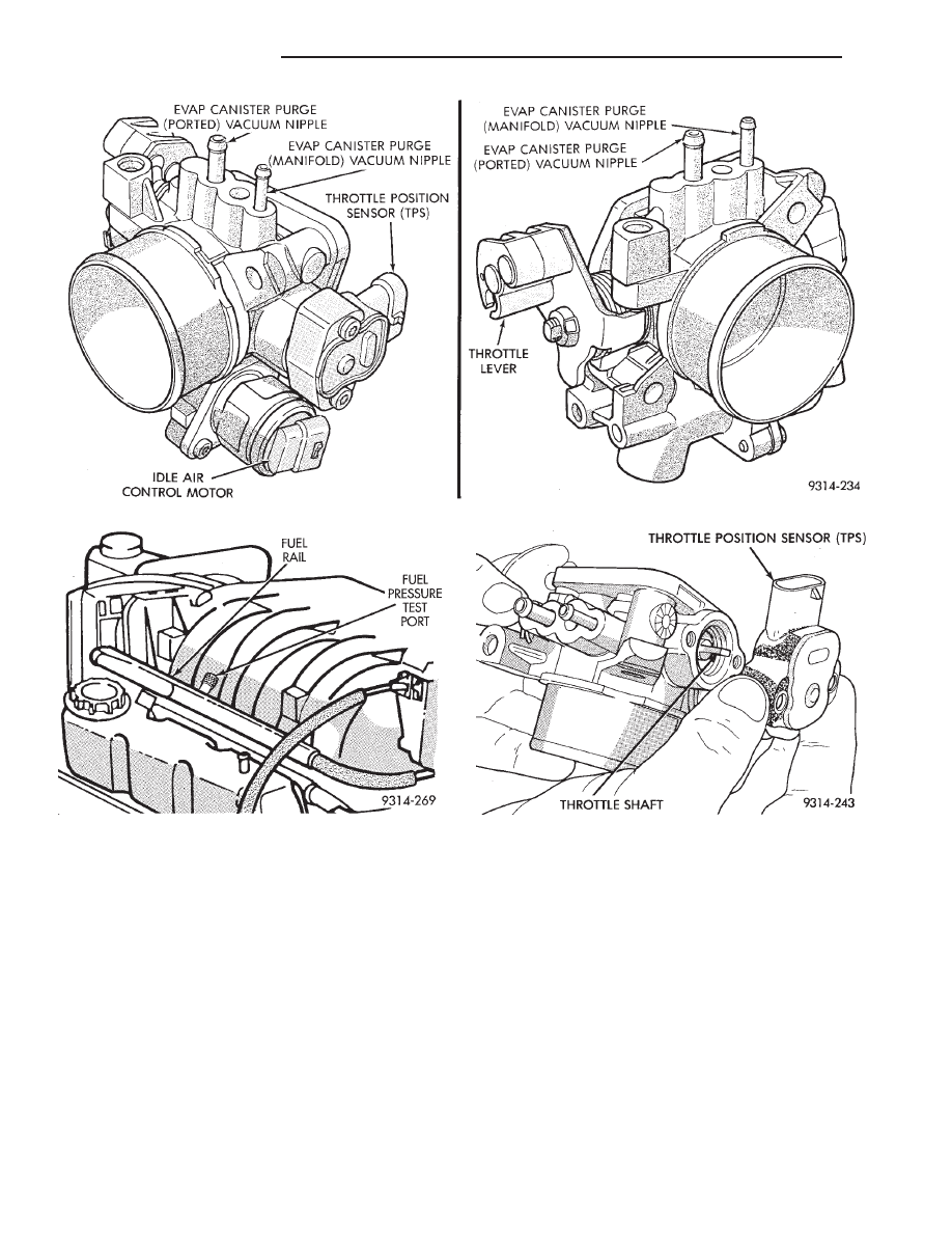
Fig. 2 Throttle Body
Fig. 3 Fuel Pressure Test Port
Fig. 4 Servicing Throttle Position Sensor
14 - 170
FUEL SYSTEMS
Ä
(4) Remove throttle cable (Fig. 6). Remove wiring
harness from throttle cable bracket and intake man-
ifold water tube.
(5) Disconnect idle air control motor and throttle
position sensor (TPS) electrical connectors (Fig. 7).
Refer to Idle Air Control Motor and Throttle Position
Sensor in this section.
(6) Remove vacuum hose harness from throttle
body (Fig. 7).
(7) Remove PCV and brake booster vacuum hoses
from air intake plenum.
(8) Remove EGR tube to intake manifold flange
bolts (Fig. 8).
(9) Remove vacuum harness connectors from in-
take plenum (Fig. 8).
(10) Remove cylinder head to intake plenum strut
(Fig. 8).
(11) Disconnect electrical connectors from the MAP
sensor and heated oxygen sensor electrical connec-
tion. Remove the engine mounted ground strap (Fig.
9).
WARNING:
WRAP
A
SHOP
TOWEL
AROUND
HOSES TO CATCH ANY GASOLINE SPILLAGE.
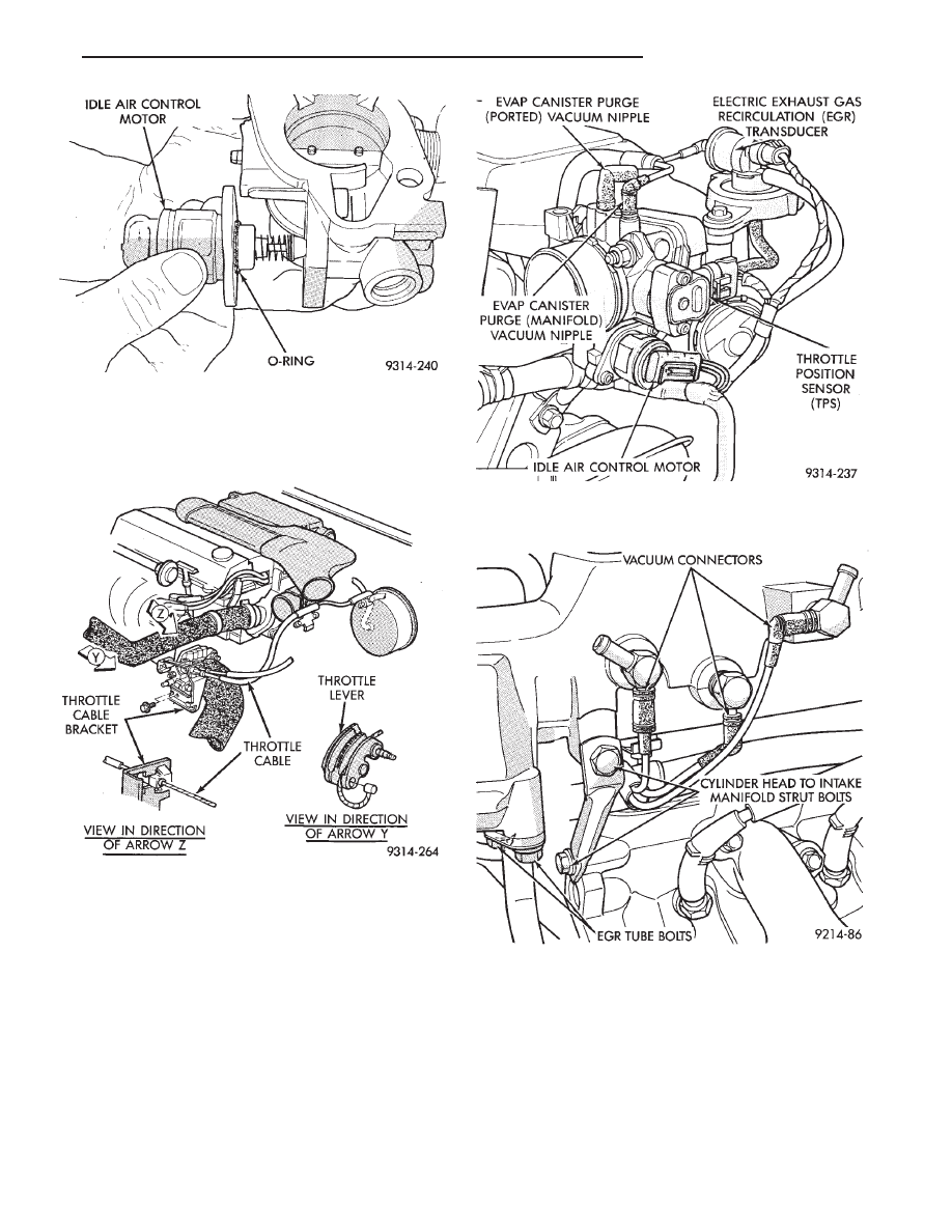
Fig. 5 Servicing Idle Air Control Motor
Fig. 6 Throttle Cable Attachment
Fig. 7 Electrical and Vacuum Connection to Throttle
Body
Fig. 8 EGR Tube
Ä
FUEL SYSTEMS
14 - 171
(12) Remove the fuel hose quick connect fittings
from the chassis tubes. Refer to Fuel Hoses, Clamps
and Quick Connect Fittings in the Fuel Delivery
Section of this Group. Place a shop towel under the
connections to absorb any fuel spilled. fittings.
(13) Remove direct ignition system (DIS) coils and
generator bracket to intake manifold bolt (Fig. 10).
(14) Remove intake mounting manifold bolts and
rotate manifold back over rear valve cover (Fig. 11).
(15) Cover intake manifold with suitable cover when
servicing (Fig. 12).
(16) Remove vacuum harness connector from Fuel
Pressure Regulator.
(17) Remove fuel tube retainer bracket screw and
fuel rail attaching bolts (Fig. 12). Spread the retainer
bracket to allow fuel tube removal clearance.
(18) Remove fuel rail injector wiring clip from the
generator bracket (Fig. 13).
(19) Disconnect camshaft position sensor, coolant
temperature sensor, and engine temperature sensors
(Fig. 13).
(20) Remove fuel rail. Be careful not to damage
the injector O-rings upon removal from their ports
(Fig. 14).
INSTALLATION
(1) Ensure
injector
holes
are
clean.
Replace
O-rings if damaged.
(2) Lubricate injector O-rings with a drop of clean
engine oil to ease installation.
(3) Put the tip of each injector into their ports.
Push the assembly into place until the injectors are
seated in the ports (Fig. 14).
(4) Install the fuel rail mounting bolts. Tighten
bolts to 22 N
Im (200 in. lbs.) torque (Fig. 12).
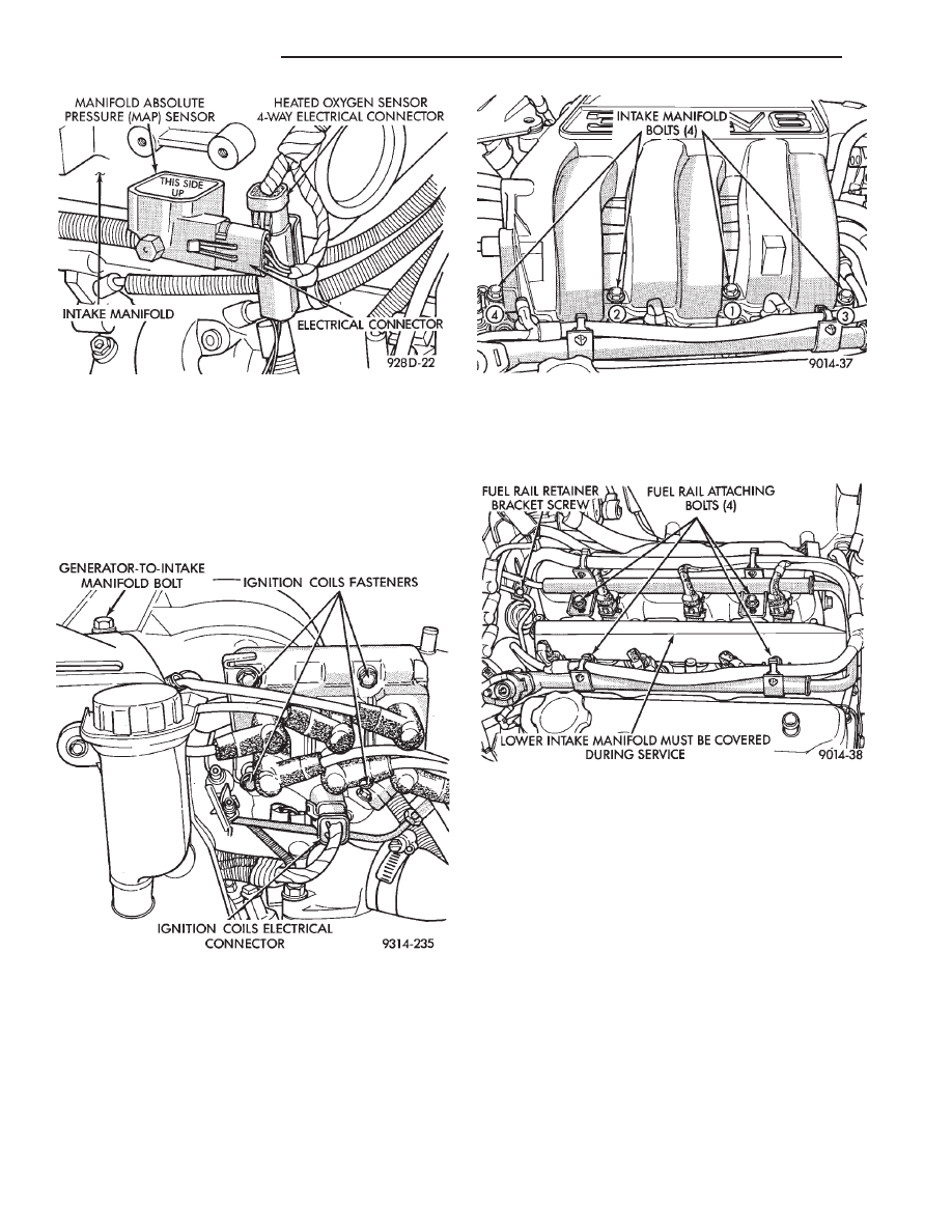
Fig. 11 Intake Manifold Bolts
Fig. 12 Fuel Rail Attaching Bolts
Fig. 9 MAP Sensor Electrical Connector
Fig. 10 Ignition Coils
14 - 172
FUEL SYSTEMS
Ä
(5) Install
fuel
tube
retaining
bracket
screw.
Tighten screw to 4 N
Im (35 in. lbs.) torque.
(6) Connect electrical connectors to camshaft posi-
tion sensor, coolant temperature sensor and engine
temperature sensors (Fig. 13).
(7) Install fuel injector harness wiring clips on the
generator bracket and intake manifold water tube
(Fig. 13).
(8) Connect vacuum line to fuel pressure regulator.
(9) Remove covering on lower intake manifold and
clean surface.
(10) Place intake manifold gasket on lower mani-
fold. Put upper manifold into place and install bolts
finger tight.
(11) Install the generator bracket to intake mani-
fold bolt and the cylinder head to intake manifold
strut bolts. (Do not tighten.)
(12) Following the tightening sequence in Figure
11, tighten intake manifold bolts to 28 N
Im (250 in.
lbs.) torque.
(13) Tighten generator bracket to intake manifold
bolt to 54 N
Im (40 ft. lbs.) torque (Fig. 13).
(14) Tighten the cylinder head to intake manifold
strut bolts to 54 N
Im (40 ft. lbs.) torque (Fig. 8).
(15) Connect ground strap, MAP and heated oxy-
gen sensor electrical connectors.
(16) Connect vacuum harness to intake plenum.
Connect PCV system hoses.
(17) Using a new gasket, connect the EGR tube to
the intake manifold plenum. Tighten screws to 22
N
Im (200 in. lbs.) torque.
(18) Clip wiring harness into the hole in the throt-
tle cable bracket.
(19) Connect electrical connectors to the throttle
position sensor (TPS) and idle air control motor.
(20) Connect vacuum harness to throttle body.
(21) Install the direct ignition system (DIS) coils.
Tighten fasteners to 12 N
Im (105 in. lbs.) torque.
(22) Install fuel hose quick connectors fittings to
chassis tubes. Refer to Fuel Hoses, Clamps and
Quick Connect Fittings in the Fuel Delivery Sec-
tion of this Group. Push the fittings onto the chas-
sis tubes until they click into place. Pull on the
fittings to ensure complete insertion. Fuel supply fit-
ting is 5/16 inch and fuel return fitting is 1/4 inch.
(23) Install throttle cable.
(24) Install air cleaner and hose assembly.
(25) Connect negative cable to battery.
CAUTION: When using the ASD Fuel System Test,
the Auto Shutdown (ASD) Relay remains energized
for either 7 minutes, until the test is stopped, or un-
til the ignition switch is turned to the Off position.
(26) With the ignition key in ON position, access
the DRBII scan tool ASD Fuel System Test to pres-
surize the fuel system. Check for leaks.
FUEL PRESSURE REGULATOR
REMOVAL
(1) Perform fuel system pressure release procedure
before attempting any repairs. Refer to Fuel Pressure
Regulator Procedure in this section.
(2) Remove fuel pressure regulator vacuum connec-
tor. (Fig. 15).
(3) Remove regulator retainer screw (Fig. 15).
(4) Remove the fuel pressure regulator retainer
(Fig. 15).
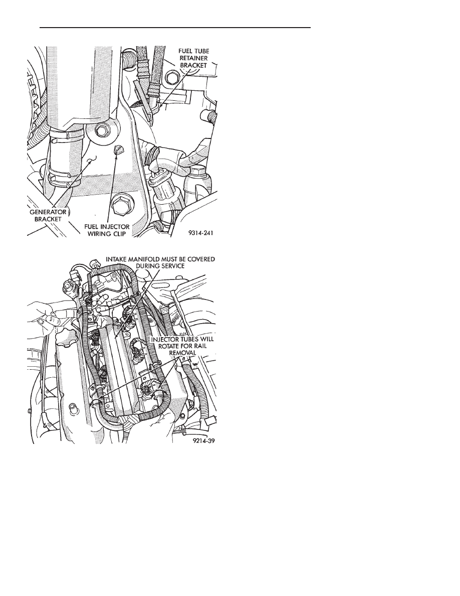
Fig. 13 Fuel Injector Wiring Clip
Fig. 14 Fuel Rail Removal
Ä
FUEL SYSTEMS
14 - 173
Нет комментариевНе стесняйтесь поделиться с нами вашим ценным мнением.
Текст