Chrysler Le Baron, Dodge Dynasty, Plymouth Acclaim. Manual — part 150
Allow the urethane at least 24 hours to cure before
returning the vehicle to use.
The windshield fence should be cleaned of old ure-
thane bonding material. Support spacers should be
cleaned and properly installed on weld studs or re-
pair screws at bottom of windshield opening.
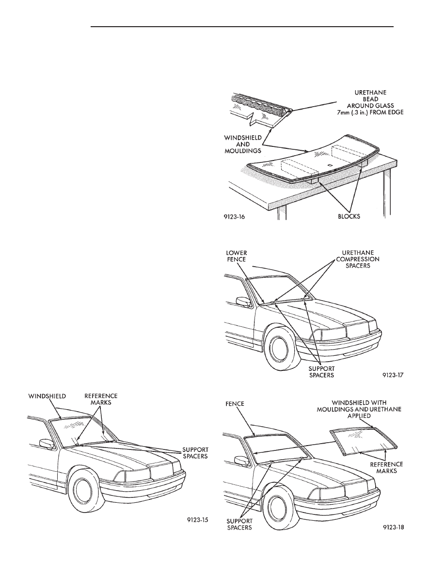
(1) Place replacement windshield into windshield
opening and position glass in the center of the open-
ing against the support spacers. Mark the glass at
the support spacers with a grease pencil or pieces of
masking tape and ink pen to use as a reference for
installation. Remove replacement windshield from
windshield opening (Fig. 3).
(2) Position the windshield inside up on a suitable
work surface with two padded, wood 10 cm by 10 cm
by 50 cm (4 in. by 4 in. by 20 in.) blocks, placed par-
allel 75 cm (2.5 ft.) apart (Fig. 4).
(3) Clean inside of windshield with Mopar Glass
Cleaner and lint-free cloth.
(4) Apply clear glass primer 25 mm (1 in.) wide
around perimeter of windshield and wipe with clean/
dry lint-free cloth.
(5) Install mouldings on windshield (Fig. 4).
(6) Apply black-out primer 15 mm (.75 in.) wide on
top and sides of windshield and 25 mm (1 in.) on bot-
tom of windshield. Allow at least three minutes dry-
ing time.
(7) Position windshield bonding compression spac-
ers on lower fence above the support spacers at the
edge of the windshield opening (Fig. 5).
(8) Apply a 10 mm (0.4 in.) bead of urethane
around perimeter of windshield along the inside of
the mouldings.
(9) With the aid of a helper, position the wind-
shield over the windshield opening. Align the refer-
ence marks at the bottom of the windshield to the
support spacers.
(10) Slowly lower windshield glass to windshield
opening fence. Guide the top moulding into proper
position if necessary. Push windshield inward to
fence spacers at bottom and until top moulding is
flush to roof line (Fig. 6).
(11) Clean excess urethane from exterior with Mo-
par, Super Clean or equivalent.
(12) Install cowl cover and wipers.
(13) Install inside rear view mirror.
(14) After urethane has cured, water test wind-
shield to verify repair.
Fig. 3 Center Windshield and Mark at Support
Spacers
Fig. 4 Work Surface Set-up and Mouldings
Installation
Fig. 5 Position Urethane Compression Spacers
Fig. 6 Lower Windshield Into Position
23 - 10
BODY
Ä

AA-VEHICLE BODY COMPONENT SERVICE
INDEX
page
page
A-Pillar and Roof Rail Mouldings
. . . . . . . . . . . . . . . . . . . . . . . 25
Body Side Moulding and Applique
. . . . . . . . . . . . . . . . . . . . . . . . . . . . . 13
Cowl Panel Trim and Scuff Plates
. . . . . . . . . . . . . . . . 24
. . . . . . . . . . . . . . . . . . . . . . . . . . . . 30
. . . . . . . . . . . . . . . . . . . . . 29
. . . . . . . . . . . . . . . . . . . . . 15
Front Door Belt Moulding and Weatherstrip
. . . . . . . . . . . . . . . . . . . . . . . . 17
Front Door Glass Channel and Run Weatherstrip
Front Door Glass Run Lower Channel
. . . . . . . . . . . . . . . . . . . . . . . . . 16
. . . . . . . . . . . . . . . . 17
Front Door Silencer and Water Shield
. . . . . . . . . . . . . . . . . . . . 14
Front Door Window Regulator/Manual
Front Door Window Regulator/Power
. . . . . . . . . . . . . . . . . . 13
. . . . . . . . . . . . . . . . . . . . . . . . . . . . 14
Front Power Door Lock Actuator
. . . . . . . . . . . . . . . . . . . . . . . . . 27
. . . . . . . . . . . . . . . . . . . . . . . . . . . . . 28
. . . . . . . . . . . . . . . . . . . . . . . . . . . 36
. . . . . . . . . . . . . . . . . . . . . . . . . . . . . . . . . . 11
. . . . . . . . . . . . . . . . . . . . . . . . . . . . . 30
. . . . . . . . . . . . . . . . . . . . . . . . 11
. . . . . . . . . . . . . . 12
Outside Front Door Latch Release Handle
Outside Rear Door Latch Release Handle
. . . . . . . . . . . . . . . . . . . . . . . . 30
. . . . . . . . . . . . . . . 27
. . . . . . . . . . . . . . . . . . . . . . . 27
. . . . . . . . . . . . . . . . . . . . 31
. . . . . . . . . . . . . . . . . . . . . 20
Rear Door Belt Moulding and Weatherstrip
. . . . . . . . . . . . . . . . . . . . . . . . . 22
Rear Door Glass Run Weatherstrip
Rear Door Glass Stationary Glass Module
. . . . . . . . . . . . . . . . . . . . . . . . . 21
Rear Door Silencer and Water Shield
. . . . . . . . . . . . . . . . . . . . . 20
Rear Door Window Regulator/Manual
Rear Door Window Regulator/Power
. . . . . . . . . . . . . . . . . . . . . . . . . . 28
. . . . . . . . . . . . . . . . . . . . . . . . . . . . . 28
. . . . . . . . . . . . . . . . . . . . . 27
. . . . . . . . . . . . . . . . . . . . . . 32
. . . . . . . . . . . . . . . . . . . . 31
. . . . . . . . . . . . . . . . . . . . 31
. . . . . . . . . . . . . . . . . . . . 31
. . . . . . . . . . . . . . . . . . . . . . . . . . . . . . 33
. . . . . . . . . . . . . . . . . . . . . . . . . 34
. . . . . . . . . . . . . . . . . . . . . . . . . . 34
. . . . . . . . . . . . . . . . . . . . . . . . . . 34
. . . . . . . . . . . . . . . . . . . 35
. . . . . . . . . . . . . . . . . . . . . 34
. . . . . . . . . . . . . . . . . . . . . . . . . . . . 35
. . . . . . . . . . . . . . . . 35
. . . . . . . . . . . . . . . . . . . . . . . . 31
GRILLE
REMOVAL (FIG. 1)
(1) Raise hood to full up position.
(2) Remove hood safety catch release rod retainer
and separate rod from grille.
(3) Remove grille end reinforcement attaching
bolts.
(4) Remove nuts holding grille to hood.
(5) Separate grille from hood.
INSTALLATION
Reverse the preceding operation.
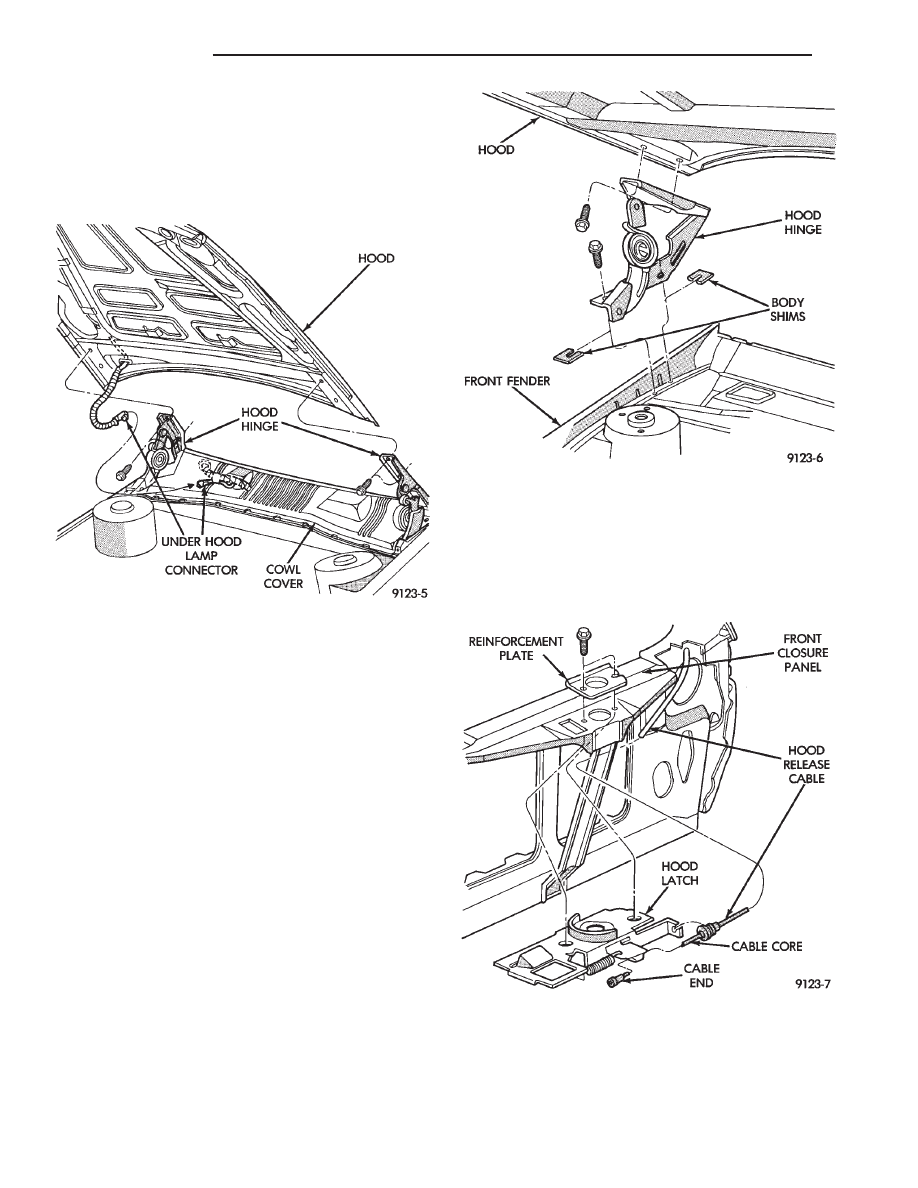
HOOD AND HINGES
HOOD REMOVAL (FIG. 2)
(1) Raise hood to full up position.
(2) Lift front edge of cowl cover on the right side of
the windshield washer bottle and disconnect the un-
der hood lamp wire connector.
(3) Mark all bolt and hinge attachment locations
with a grease pencil or other suitable device to pro-
vide reference marks for installation. When install-
ing hood, align all marks and secure bolts. The hood
should be aligned to 4 mm (0.160 in.) gap to the front
fenders and flush across the top surfaces along fend-
ers.
(4) Remove the top hood to hinge attaching bolts
and loosen the bottom bolts until they can be re-
moved by hand.
Fig. 1 Grille Assembly
Ä
AA-BODY
23 - 11
(5) With assistance of a helper at the opposite side
of the vehicle to support the hood, remove the bottom
hood to hinge attaching bolts. Separate the hood
from the vehicle.
HOOD INSTALLATION
Reverse the preceding operation.
HOOD HINGE REMOVAL (FIG. 3)
(1) Support hood on the side that requires hinge
replacement.
(2) Mark all bolt and hinge attachment locations
with a grease pencil or other suitable device to pro-
vide reference marks for installation. When install-
ing hood hinge, align all marks and secure bolts. The
hood should be aligned to 4 mm (0.160 in.) gap to the
front fenders and flush across the top surfaces along
fenders. Shims can be added or removed under hood
hinge to achieve proper hood height.
(3) Remove hood to hinge attaching bolts.
(4) Remove hood hinge to front fender attaching
bolts and separate hinge from vehicle.
HOOD HINGE INSTALLATION
Reverse the preceding operation. If necessary, paint
new hinge before installation.
HOOD LATCH AND RELEASE CABLE
HOOD LATCH REMOVAL (FIG. 4)
(1) Raise hood top the full up position.
(2) Remove hood latch attaching bolts holding
latch to radiator closure panel and separate from ve-
hicle.
(3) Pry release cable casing attachment from slot
receiver on latch, disengage cable end from latch arm
hook.
HOOD LATCH INSTALLATION
Reverse the preceding operation.
HOOD LATCH RELEASE CABLE REMOVAL
(FIG. 5)
(1) Raise hood to the full up position.
Fig. 2 Hood Assembly
Fig. 3 Hood Hinge Assembly
Fig. 4 Hood Latch Assembly
23 - 12
AA-BODY
Ä

(2) Remove push-in fasteners holding hood latch
cover to radiator closure panel and separate cover
from vehicle.
(3) Disconnect hood release cable casing and cable
end from hood latch assembly. Refer to Hood Latch
Removal procedure in this section.
(4) Remove hood latch release cable handle attach-
ing bolts from under left lower edge of instrument
panel.
(5) Disengage release cable rubber grommet from
engine compartment dash panel behind instrument
panel.
(6) Rout cable assembly through engine compart-
ment around battery, under fender lip, under relay
bank, and under wiring harnesses, toward dash
panel. Push cable through access hole in dash panel
under the brake master cylinder, into passenger com-
partment.
HOOD LATCH RELEASE CABLE
INSTALLATION
Reverse the preceding operation.
COWL COVER
REMOVAL (FIG. 6)
(1) Raise hood to full up position.
(2) Disconnect windshield washer hoses from wiper
arms.
(3) Remove windshield wiper arm assemblies. Re-
fer to Group 8K, Windshield Wiper and Washer Sys-
tems.
(4) Remove plastic expanding type fasteners hold-
ing cowl cover to cowl, below windshield.
(5) Lift back of cowl cover and slide cover rearward
from under dash panel to hood seal and separate
cover from vehicle.
INSTALLATION
Reverse the preceding operation.
FRONT END SPLASH SHIELDS
FRONT WHEELHOUSE SPLASH SHIELD
REMOVAL (FIG. 7)
(1) Hoist vehicle and support on suitable safety
stands.
(2) Remove front wheel assembly.
(3) Remove push-in fasteners holding front wheel-
house splash shield to fender opening lip and inner
wheelhouse area.
(4) Separate wheelhouse splash shield from vehi-
cle.
FRONT WHEELHOUSE SPLASH SHIELD
INSTALLATION
Reverse the preceding operation.
TRANSAXLE SPLASH SHIELD REMOVAL (FIG.
7)
(1) Remove one front wheelhouse splash shield
push-in fastener and separate wheelhouse splash
shield from transaxle splash shield.
(2) Remove transaxle splash shield attaching bolts
and separate transaxle splash shield from vehicle.
TRANSAXLE SPLASH SHIELD INSTALLATION
Reverse the preceding operation.
ENGINE DRIVE BELT SPLASH SHIELD
REMOVAL (FIG. 8)
(1) Hoist vehicle and support on suitable safety
stands.
(2) Remove bolts holding engine drive belt splash
shield to right frame rail.
(3) Separate drive belt splash shield from vehicle.
ENGINE DRIVE BELT SPLASH SHIELD
INSTALLATION
Reverse the preceding operation.
Fig. 5 Hood Latch Release Cable Assembly
Fig. 6 Cowl Cover Assembly
Ä
AA-BODY
23 - 13
Нет комментариевНе стесняйтесь поделиться с нами вашим ценным мнением.
Текст