Chrysler Le Baron, Dodge Dynasty, Plymouth Acclaim. Manual — part 151

FRONT FENDER
REMOVAL (FIG. 9)
(1) Remove front side marker lamp assembly. Re-
fer to Group 8L, Lamps for instructions.
(2) Remove front bumper as necessary to gain
clearance to remove front fender. Refer to Front
Bumper Removal paragraph in this section.
(3) Remove front wheelhouse splash shield. Refer
to Front Wheelhouse Splash Shield Removal para-
graph of this section.
(4) Remove rocker panel moulding as necessary to
clear front fender. Refer to Body Side Moulding and
Applique Removal paragraph in this section.
(5) Remove bolts holding bottom front fender at
rear of wheel opening.
(6) Remove bolt holding front fender at rear of
wheelhouse.
(7) Remove bolt holding front fender at top of front
door opening.
(8) Remove bolts holding front fender to front
lower brace and under radiator closure panel.
(9) Remove bolts holding front fender to front of
radiator closure panel.
(10) Raise hood and support hood on a suitable
holding device. Mark hinge for installation indexing.
Remove lower hood hinge attaching bolts and sepa-
rate hinge from front fender. Refer to Hood Hinge
Removal paragraph in this section.
(11) Remove bolts holding front fender to inner
wheelhouse along hood opening.
(12) Separate front fender from vehicle.
INSTALLATION
Reverse the preceding operation. Align front fender
to achieve a 4 mm (0.160 in) gap to hood edge and 6
mm (0.240 in) gap to front door edge. All surfaces
across gaps should be flush.
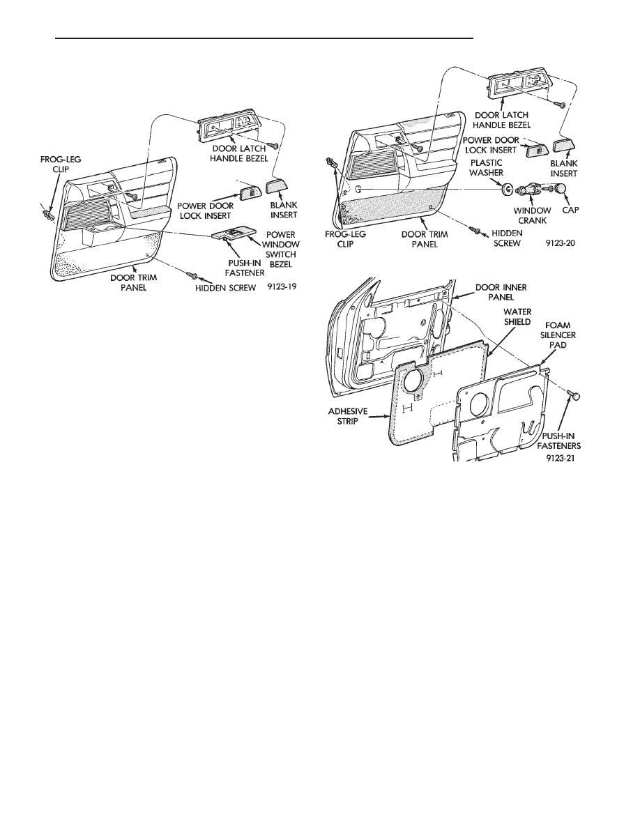
FRONT DOOR TRIM PANEL
DOOR TRIM PANEL WITH POWER WINDOWS
REMOVAL (FIG. 10)
(1) Move glass to down position.
(2) Disconnect battery negative cable.
(3) Using a suitable prying tool, lift upward at
front of power window switch bezel and disengage be-
zel from clip in door panel. Disconnect wire connector
from back of switch.
(4) Remove door latch handle bezel insert. Discon-
nect power door lock switch wire connector, if
equipped. Remove screws holding handle bezel to
trim panel and separate bezel from door.
(5) Remove screw holding armrest pull handle to
door through door latch handle bezel opening.
(6) Remove hidden screw from in carpet at rear
lower corner of trim panel.
(7) Using a suitable trim clip tool, disengage frog
leg clips at the ends and bottom of trim panel. After
all trim clips are loose, push inward at the top of the
trim panel and lift upward to disengage barb fasten-
ers at top of panel. Separate trim from door.
Fig. 7 Front Wheelhouse and Transaxle Splash
Shields
Fig. 8 Engine Drive Belt Splash Shield
Fig. 9 Front Fender Assembly
23 - 14
AA-BODY
Ä
DOOR TRIM PANEL WITH POWER WINDOWS
INSTALLATION
Reverse the preceding operation.
DOOR TRIM PANEL WITH MANUAL WINDOWS
REMOVAL (FIG. 11)
(1) Open door glass to full down position.
(2) Disconnect battery negative cable.
(3) Remove window crank cap, attaching screw,
and handle.
(4) Remove door latch handle bezel insert. Discon-
nect power door lock switch wire connector, if
equipped. Remove screws holding handle bezel to
trim panel and separate bezel from door.
(5) Remove screw holding armrest pull handle to
door through door latch handle bezel opening.
(6) Remove hidden screw from in carpet at rear
lower corner of trim panel.
(7) Using a suitable trim clip tool, disengage frog
leg clips at the ends and bottom of trim panel. After
all trim clips are loose, push inward at the top of the
trim panel and lift upward to disengage barb retain-
ers at top of panel. Separate trim from door.
DOOR TRIM PANEL WITH MANUAL WINDOWS
INSTALLATION
Reverse the preceding operation.
FRONT DOOR SILENCER AND WATER SHIELD
REMOVAL (FIG. 12)
(1) Remove front door trim panel.
(2) Remove push-in fasteners holding silencer pad
to door inner panel and separate silencer from door.
(3) Pull water shield from adhesive around perim-
eter of door inner panel.
INSTALLATION
Reverse the preceding operation.
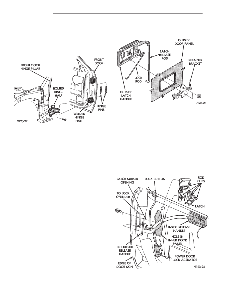
FRONT DOOR AND HINGE
The front door hinge is welded to the door and
bolted to the hinge pillar. The door half of the hinge
pivots on a removable hinge pin. The hinge pin is
driven in from the bottom on the top hinge and from
the top on the bottom hinge. All adjustments to the
hinge are performed on the hinge pillar half of the
hinge. If the welded half of the hinge must be bent to
align door, consult an authorized body repair facility.
FRONT DOOR REMOVAL (FIG. 13)
(1) Remove door trim panel, silencer pad, and wa-
ter shield.
(2) Disconnect all wire connectors and wire har-
ness hold downs inside door and push wire harness
through access hole in front of door into hinge pillar
opening.
(3) Open door and support door on a suitable lift-
ing device.
(4) Drive bottom hinge pin upward and remove pin
from hinge.
(5) Drive top hinge pin downward and remove pin
from hinge.
Fig. 10 Front Door Trim Panel with Power Windows
Fig. 11 Front Door Trim Panel with Manual Windows
Fig. 12 Front Door Silencer and Water Shield
Ä
AA-BODY
23 - 15
(6) Separate door from vehicle.
FRONT DOOR INSTALLATION
Reverse the preceding operation. The door should
not require re-alignment. If door does need align-
ment, refer to Front Door Hinge Installation para-
graph in this section.
FRONT DOOR HINGE REMOVAL (FIG. 14)
(1) Remove front fender wheelhouse splash shield.
Refer to Front Wheelhouse Splash Shield Removal
paragraph in this section.
(2) Support door on a suitable lifting device.
(3) Drive out hinge pin on the effected hinge.
(4) Remove bolts holding hinge to hinge pillar and
separate hinge form vehicle.
FRONT DOOR HINGE INSTALLATION
Reverse the preceding operation. Align door to
achieve 6 mm (0.240 in.) gap to all surrounding pan-
els and flush across gaps.
OUTSIDE FRONT DOOR LATCH RELEASE HANDLE
OUTSIDE FRONT DOOR LATCH RELEASE
HANDLE REMOVAL (FIG. 14)
(1) Remove front door trim panel, silencer pad, and
water shield.
(2) Raise door glass to full up position.
(3) Disconnect security alarm switch and illumi-
nated entry switch from back of outside front door
latch release handle, if equipped. For additional in-
formation refer to Group 8Q, Vehicle Theft Security
System
(4) Disconnect lock rod and latch release rod from
door latch assembly.
(5) Remove nuts holding outside door latch handle
to retainer bracket and separate bracket from door.
(6) Swing lock rod upward, parallel to back of
latch handle, and separate latch handle from door
panel.
OUTSIDE FRONT DOOR LATCH RELEASE
HANDLE INSTALLATION
Reverse the preceding operation.
FRONT DOOR LATCH
REMOVAL (FIG. 15)
(1) Remove front door trim panel, silencer pad and
water shield.
(2) Raise door glass to full up position.
(3) Disconnect all actuator rods from door latch as-
sembly.
(4) Remove screws holding door latch assembly to
inner door rear panel and separate latch from door.
INSTALLATION
Reverse the preceding operation.
Fig. 13 Front Door Assembly
Fig. 14 Outside Front Door Latch Release Handle
Fig. 15 Front Door Latch Assembly
23 - 16
AA-BODY
Ä
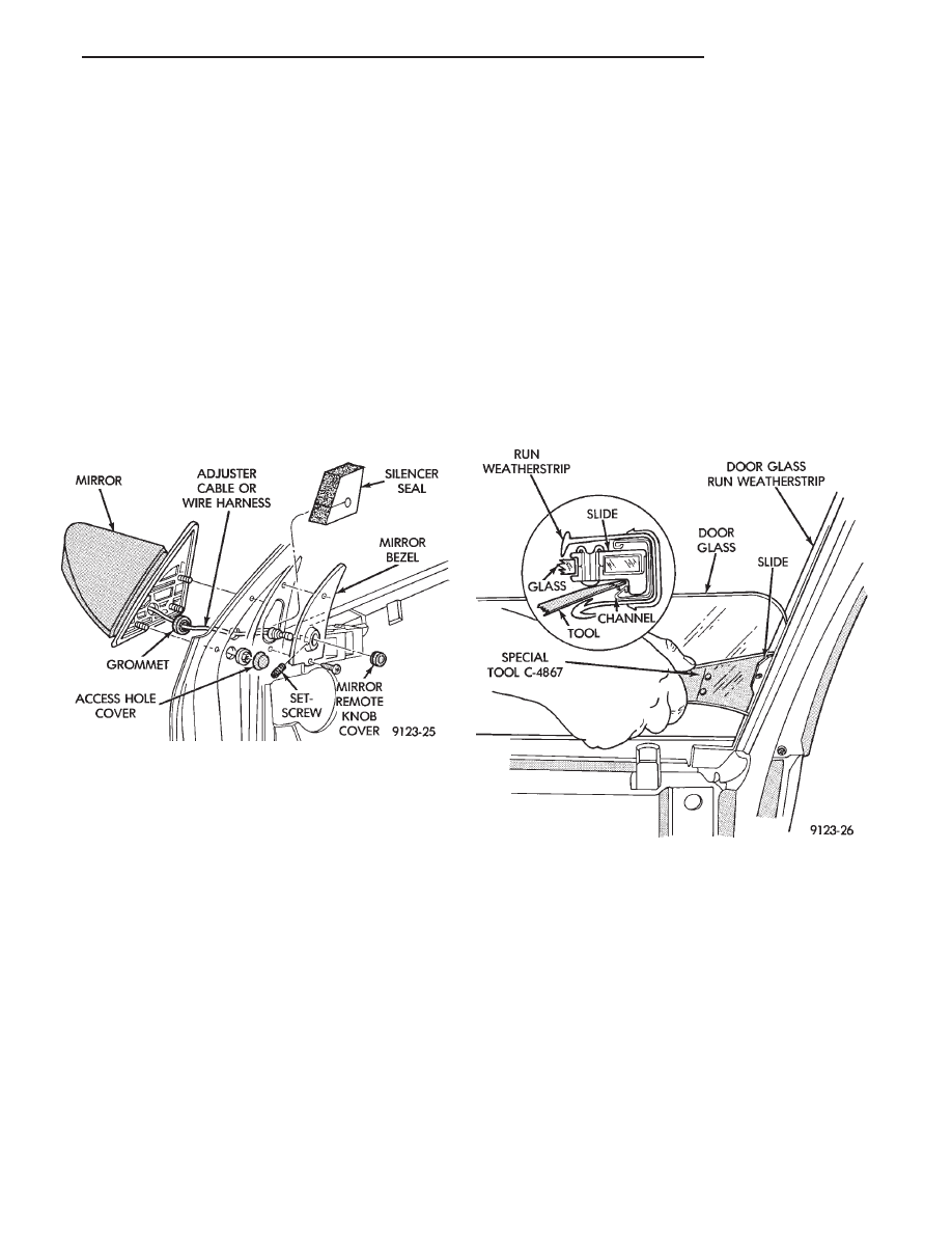
FRONT DOOR SIDE VIEW MIRROR
REMOVAL (FIG. 16)
(1) Remove front door trim panel.
(2) Remove side view mirror remote adjusting
knob cover, if equipped.
(3) Remove screws holding mirror bezel to door
frame and separate bezel from door. Loosen set-screw
holding bezel to mirror adjuster cable, if equipped.
(4) Remove silencer seal from door frame behind
mirror bezel.
(5) Disconnect power mirror wire connector, if
equipped.
(6) Remove access hole cover.
(7) Remove nuts holding mirror to door frame and
separate mirror from door.
INSTALLATION
Reverse the preceding operation.
FRONT DOOR GLASS
REMOVAL (FIG. 17)
(1) Remove door trim panel, silencer pad, and wa-
ter shield.
(2) Position door glass half way up in door glass
opening.
(3) Insert door glass removal tool C-4867 between
the glass slide and channel retaining lip at approxi-
mately 50 mm (2 in.) down from top rearward corner
of glass. Push handle of tool toward glass to open
channel. Push downward at the front of the glass to
separate the slide from the channel.
(4) Insert door glass removal tool C-4867 between
the glass slide and channel retaining lip at approxi-
mately 50 mm (2 in.) up from bottom rearward cor-
ner of glass through opening in inner door panel.
Push handle of tool toward glass to open channel.
Pull upward at front of glass to separate the slide
from the channel. Do not allow upper slide to snap
bank into channel.
(5) Rotate front of glass downward and slide glass
forward to separate glass lift channel from regulator
lift arm roller.
(6) Remove door glass through opening at top of
door.
INSTALLATION
(1) Lower door glass into opening at top of door.
(2) Tip rear of glass downward and insert window
regulator lift arm roller into glass lift channel.
(3) Guide door glass into glass run weatherstrip at
front of door.
(4) Push top of glass rearward to snap top slide
into glass run channel.
(5) Push downward at front of glass to snap bottom
slide into glass run channel.
(6) Install water shield, silencer pad and trim
panel.
FRONT DOOR BELT MOULDING AND
WEATHERSTRIP
BELT MOULDING AND WEATHERSTRIP
REMOVAL (FIG. 18)
(1) Remove trim panel, silencer pad, and water
shield as necessary to gain access to belt moulding
attaching screws.
(2) Remove door glass.
(3) Remove screws holding belt moulding and
weatherstrip to outer door panel and separate moul-
ding from door.
BELT MOULDING AND WEATHERSTRIP
INSTALLATION
Reverse the preceding operation.
Fig. 16 Front Door Side View Mirror
Fig. 17 Front Door Glass
Ä
AA-BODY
23 - 17
Нет комментариевНе стесняйтесь поделиться с нами вашим ценным мнением.
Текст