Chrysler Le Baron, Dodge Dynasty, Plymouth Acclaim. Manual — part 109
Unless the condition is obvious, like no drive in D
range first gear only. The transaxle should never be
disassembled until hydraulic pressure tests have
been performed.
HYDRAULIC PRESSURE TESTS
Pressure testing is a very important step in the di-
agnostic procedure. These tests usually reveal the
cause of most transaxle problems.
Before performing pressure tests, be certain that
fluid level and condition, and control cable adjust-
ments have been checked and approved.
Fluid must be at operating temperature (150 to 200
degrees F.).
Install an engine tachometer, raise vehicle on hoist
which allows front wheels to turn, and position ta-
chometer so it can be read.
Disconnect throttle cable and shift cable from tran-
saxle levers so they can be controlled from outside
the vehicle.
Attach 150 psi gauges to ports required for test be-
ing conducted. A 300 psi gauge (C-3293) is required
for reverse pressure test at rear servo.
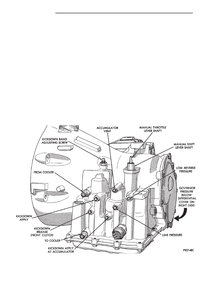
Test port locations are shown in (Fig. 3).
TEST ONE (SELECTOR IN 1)
(1) Attach gauges to line and low-reverse ports
(Fig. 3).
(2) Operate engine at 1000 rpm for test.
(3) Move selector lever on transaxle all the way
rearward (1 position).
(4) Read pressures on both gauges as throttle lever
on transaxle is moved from full clockwise position to
full counterclockwise position.
(5) Line pressure should read 52 to 58 psi with
throttle lever clockwise and gradually increase, as le-
ver is moved counterclockwise, to 80 to 88 psi.
(6) Low-reverse pressure should read the same as
line pressure within 3 psi.
(7) This tests pump output, pressure regulation,
and condition of rear clutch and rear servo hydraulic
circuits.
TEST TWO (SELECTOR IN 2)
(1) Attach one gauge to line pressure port and
tee another gauge into lower cooler line fitting. This
will allow you to read lubrication pressure (Fig 3).
(2) Operate engine at 1000 rpm for test.
Fig. 3 Transaxle (Left Side)
21 - 42
TRANSAXLE
Ä
(3) Move selector lever on transaxle one detent
forward from full rearward position. This is selector
2 position.
(4) Read pressures on both gauges as throttle lever
on transaxle is moved from full clockwise position to
full counterclockwise position.
(5) Line pressure should read 52 to 58 psi with
throttle lever clockwise and gradually increase, as le-
ver is moved counterclockwise, to 80 to 88 psi.
(6) Lubrication pressure should be 10 to 25 psi
with lever clockwise and 10 to 35 psi with lever full
counterclockwise.
(7) This tests pump output, pressure regulation,
and condition of rear clutch and lubrication hydrau-
lic circuits.
TEST THREE (SELECTOR IN D)
(1) Attach gauges to line and kickdown release
ports (Fig. 3).
(2) Operate engine at 1600 rpm for test.
(3) Move selector lever on transaxle two detents
forward from full rearward position. This is selector
D position.
(4) Read pressures on both gauges as throttle lever
on transaxle is moved from full clockwise position to
full counterclockwise position.
(5) Line pressure should read 52 to 58 psi with
throttle lever clockwise and gradually increase, as le-
ver is moved counterclockwise to 80 to 88 psi.
(6) Kickdown release is pressurized only in direct
drive and should be same as line pressure within 3
psi, up to kickdown point.
(7) This tests pump output, pressure regulation,
and condition of rear clutch, front clutch, and hy-
draulic circuits.
TEST FOUR (SELECTOR IN REVERSE)
(1) Attach 300 psi gauge to low-reverse port (Fig.
3).
(2) Operate engine at 1600 rpm for test.
(3) Move selector lever on transaxle four detents
forward from full rearward position. This is selector
R position.
(4) Low-reverse pressure should read 180 to 220
psi with throttle lever clockwise and gradually in-
crease, as lever is moved counterclockwise to 260 to
300 psi.
(5) This tests pump output, pressure regulation,
and condition of front clutch and rear servo hydraulic
circuits.
(6) Move selector lever on transaxle to D position
to check that low-reverse pressure drops to zero.
(7) This tests for leakage into rear servo, due to
case porosity, which can cause reverse band burn
out.
TEST RESULT INDICATIONS
(1) If proper line pressure, minimum to maximum, is
found in any one test, the pump and pressure regulator
are working properly.
(2) Low pressure in D, 1, and 2 but correct pressure
in R indicates rear clutch circuit leakage.
(3) Low pressure in D and R but correct pressure in
1 indicates front clutch circuit leakage.
(4) Low pressure in R and 1 but correct pressure in
2 indicates rear servo circuit leakage.
(5) Low line pressure in all positions indicates a
defective pump, a clogged filter, or a stuck pressure
regulator valve.
GOVERNOR PRESSURE
Test only if transaxle shifts at wrong vehicle speeds
when throttle cable is correctly adjusted.
(1) Connect a 0-150 psi pressure gauge to governor
pressure take-off point, located at lower right side of
case, below differential cover (Fig. 3).
(2) Operate transaxle in third gear to read pres-
sures. The governor pressure should respond smoothly
to changes in mph and should return to
0 to 3 psi when vehicle is stopped. High pressure at
standstill (above 3 psi) will prevent the transaxle from
downshifting.
THROTTLE PRESSURE
No gauge port is provided for throttle pressure.
Incorrect throttle pressure should only be suspected if
part throttle upshift speeds are either delayed or occur
too early, with a correctly adjusted throttle cable.
Engine runaway on either upshifts or downshifts can
also be an indicator of incorrect (low) throttle pressure
setting, or misadjusted throttle cable.
In no case should throttle pressure be adjusted until
the transaxle throttle cable adjustment has been veri-
fied to be correct.
CLUTCH AND SERVO AIR PRESSURE TESTS
A no drive condition might exist even with correct
fluid pressure, because of inoperative clutches or
bands. The inoperative units, clutches, bands, and
servos can be located through a series of tests by
substituting air pressure for fluid pressure (Fig. 4).
The front and rear clutches, kickdown servo, and
low-reverse servo may be tested by applying air pres-
sure to their respective passages after
the valve body assembly has been removed. To make
air pressure tests, proceed as follows:
Compressed air supply must be free of all dirt
or moisture. Use a pressure of 30 psi.
Remove oil pan and valve body See Disassembly-
Subassembly Removal.
FRONT CLUTCH
Apply air pressure to front clutch apply passage and
listen for a dull thud which indicates that front
Ä
TRANSAXLE
21 - 43

clutch is operating. Hold air pressure on for a few
seconds and inspect system for excessive oil leaks.
REAR CLUTCH
Apply air pressure to rear clutch apply passage
and listen for a dull thud which indicates that rear
clutch is operating. Also inspect for excessive oil
leaks. If a dull thud cannot be heard in the clutches,
place finger tips on clutch housing and again apply
air pressure. Movement of piston can be felt as the
clutch is applied.
KICKDOWN SERVO (FRONT)
Direct air pressure into kickdown servo ON pas-
sage. Operation of servo is indicated by a tightening
of front band. Spring tension on servo piston should
release the band.
LOW AND REVERSE SERVO (REAR)
Direct air pressure into LOW-REVERSE SERVO
APPLY passage. Operation of servo is indicated by a
tightening of rear band. Spring tension on servo pis-
ton should release the band.
If clutches and servos operate properly, no upshift
or erratic shift conditions indicate that malfunctions
exist in the valve body.
FLUID LEAKAGE-TRANSAXLE TORQUE
CONVERTER HOUSING AREA
(1) Check for Source of Leakage.
Since fluid leakage at or around the torque con-
verter area may originate from an engine oil leak,
the area should be examined closely. Factory fill
fluid is dyed red and, therefore, can be distinguished
from engine oil.
(2) Prior to removing the transaxle, perform the
following checks:
• When leakage is determined to originate from the
transaxle, check fluid level prior to removal of the
transaxle and torque converter.
• High oil level can result in oil leakage out the
vent in the dipstick. If the fluid level is high, adjust
to proper level.
After performing this operation, inspect for leak-
age. If a leak persists, perform the following opera-
tion on the vehicle to determine if it is the torque
converter or transaxle that is leaking.
LEAKAGE TEST PROBE
(1) Remove torque converter housing dust shield.
(2) Clean the inside of torque converter housing
(lower area) as dry as possible. A solvent spray fol-
lowed by compressed air drying is preferable.
Fig. 4 Air Pressure Tests
21 - 44
TRANSAXLE
Ä
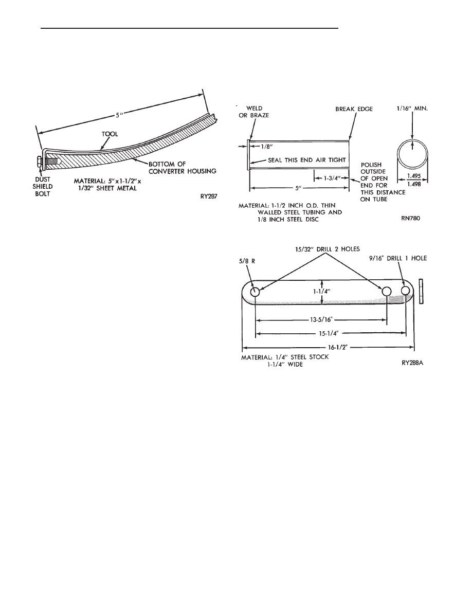
(3) Fabricate and fasten test probe (Fig. 5) securely
to convenient dust shield bolt hole. Make certain
torque converter is cleared by test probe. Tool must
be clean and dry.
(4) Run engine at approximately 2,500 rpm with
transaxle in neutral, for about 2 minutes. Transaxle
must be at operating temperature.
(5) Stop engine and carefully remove tool.
(6) If upper surface of test probe is dry, there is no
torque converter leak. A path of fluid across probe
indicates a torque converter leak. Oil leaking under
the probe is coming from the transaxle pump area.
(7) Remove transaxle and torque converter assem-
bly from vehicle for further investigation.The fluid
should be drained from the transaxle. Reinstall oil
pan (with MOPAR
t Adhesive Sealant) at specified
torque.
Possible sources of transaxle torque converter area
fluid leakage are:
(1) Torque converter hub seal.
(a) Seal lip cut, check torque converter hub fin-
ish.
(b) Bushing moved and/or worn.
(c) Oil return hole in pump housing plugged or
omitted.
(d) Seal worn out (high-mileage vehicles).
(2) Fluid leakage at the outside diameter from
pump housing O-ring.
(3) Fluid leakage at the pump to case bolts. Check
condition of washers on bolts and use new bolts if
necessary.
(4) Fluid leakage due to case or pump housing po-
rosity.
TORQUE CONVERTER LEAKAGE
Possible sources of torque converter leakage are:
• Torque converter weld leaks at the outside diame-
ter (peripheral) weld.
• Torque converter hub weld.
• Torque converter impeller shell cracked adjacent
to hub.
• At drive lug welds.
Hub weld is inside and not visible. Do not
attempt to repair. Replace torque converter.
AIR PRESSURE TEST OF TRANSAXLE
Fabricate equipment needed for test as shown in
figures 6 and 7.
The transaxle should be prepared for pressure test as
follows after removal of the torque converter:
(1) Install a dipstick bore plug and plug oil cooler
line fitting (lower fitting).
(2) With rotary motion, install converter hub seal
cup over input shaft. It must go through the converter
hub seal until the cup bottoms against the pump gear
lugs. Before use, inspect hub seal cup (Fig. 6) for nicks
or burrs that could damage seal. Secure with cup
retainer strap (Fig. 7) using starter upper hole and
opposite bracket hole.
(3) Attach and clamp hose from nozzle of Tool C-4080
to the upper cooler line fitting position in case.
CAUTION: Do not, under any circumstances, pressur-
ize a transaxle to more than 10 psi.
(4) Pressurize the transaxle using Tool C-4080 until
the pressure gauge reads 8 psi. Position transaxle
Fig. 5 Leak Locating Test Probe Tool
Fig. 6 Torque Converter Hub Seal Cup
Fig. 7 Hub Seal Cup Retaining Strap
Ä
TRANSAXLE
21 - 45
Нет комментариевНе стесняйтесь поделиться с нами вашим ценным мнением.
Текст