Chrysler Le Baron, Dodge Dynasty, Plymouth Acclaim. Manual — part 10
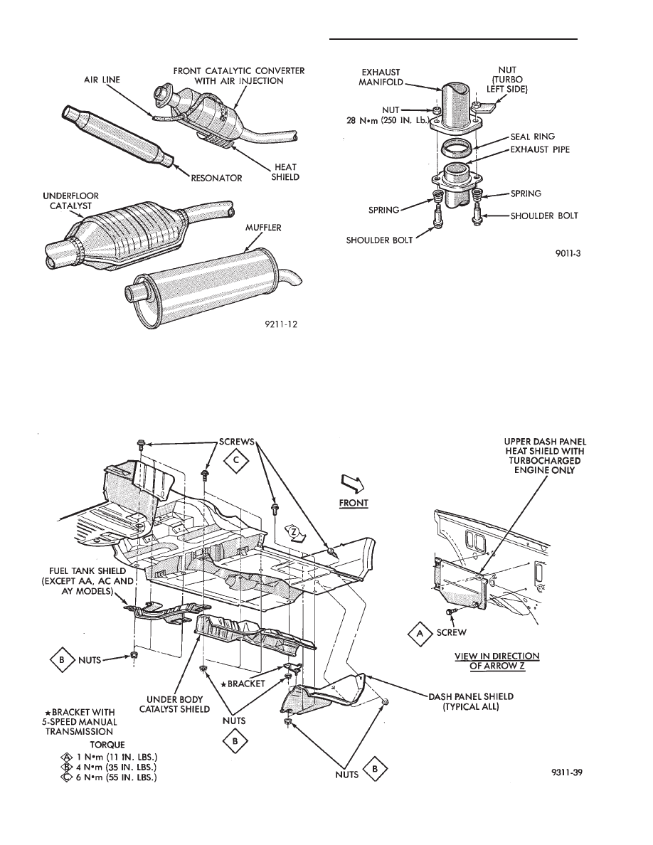
HEAT SHIELDS
Heat shields (Fig. 4) are needed to protect both the
car and the environment from the high temperatures
developed in the vicinity of the catalytic converters.
2.2/2.5L engines equipped with manual transmission
where air is injected into the catalytic converter’s, a
heat shield is welded on the lower bottom of the front
converter.
Refer to Body and Sheet Metal, Group 23 for ser-
vice procedures.
Fig. 3 Ball Joint Connection
Fig. 4 Heat Shield Installation
Fig. 2 Exhaust System Components
11 - 2
EXHAUST SYSTEM AND INTAKE MANIFOLD
Ä

CAUTION: Avoid application of rust prevention
compounds or undercoating materials to exhaust
system floor pan heat shields on cars if equipped.
Light overspray near the edges is permitted. Appli-
cation of coating will greatly reduce the efficiency
of the heat shields resulting in excessive floor pan
temperatures and objectionable fumes.
The combustion reaction caused by the catalyst re-
leases additional heat in the exhaust system. Caus-
ing temperature increases in the area of the reactor
under severe operating conditions. Such conditions
can exist when the engine misfires or otherwise does
not operate at peak efficiency. Do not remove spark
plug wires from plugs or by any other means short
out cylinders if exhaust system is equipped with cat-
alytic converter. Failure of the catalytic converter
can occur due to temperature increases caused by un-
burned fuel passing through the converter.
The use of the catalysts also involves some non-au-
tomotive problems. Unleaded gasoline must be used
to avoid poisoning the catalyst core. Do not allow en-
gine to operate above 1200 RPM in neutral for ex-
tended periods over 5 minutes. This condition may
result in excessive exhaust system/floor pan temper-
atures because of no air movement under the vehicle.
EXHAUST GAS RECIRCULATION (EGR)
SYSTEM
To assist in the control of oxides of nitrogen (NOx)
in engine exhaust, some engines are equipped with
an exhaust gas recirculation system. The use of ex-
haust gas to dilute incoming air/fuel mixtures lowers
peak flame temperatures during combustion, thus
limiting the formation of NOx.
Exhaust gases are taken from openings in the ex-
haust gas crossover passage in the intake manifold.
REFER TO SECTION 25 EMISSION SYSTEMS
FOR A COMPLETE DESCRIPTION, DIAGNOSIS
AND SERVICE PROCEDURES ON THE EXHAUST
GAS RECIRCULATION SYSTEM AND COMPO-
NENTS.
EXHAUST SYSTEM DIAGNOSIS
Ä
EXHAUST SYSTEM AND INTAKE MANIFOLD
11 - 3

SERVICE PROCEDURES
INDEX
page
page
Exhaust Pipes, Mufflers and Tailpipes
. . . . . . . . . . 4
Intake and Exhaust Manifolds Service—TBI Engine
Intake and Exhaust Manifolds—Flexible Fuel Engine
Intake and Exhaust Manifolds—TBI Engine
. . . . . . 5
Intake/Exhaust Manifold Service—3.0L Engine
. . . 13
Intake/Exhaust Manifold Service—3.3/3.8L Engines
Intake/Exhaust Manifolds and Turbocharger
Service—Turbo III Engine
. . . . . . . . . . . . . . . . . . 9
Intake/Exhaust Manifolds Service—Flexible Fuel
Engines
. . . . . . . . . . . . . . . . . . . . . . . . . . . . . . . 7
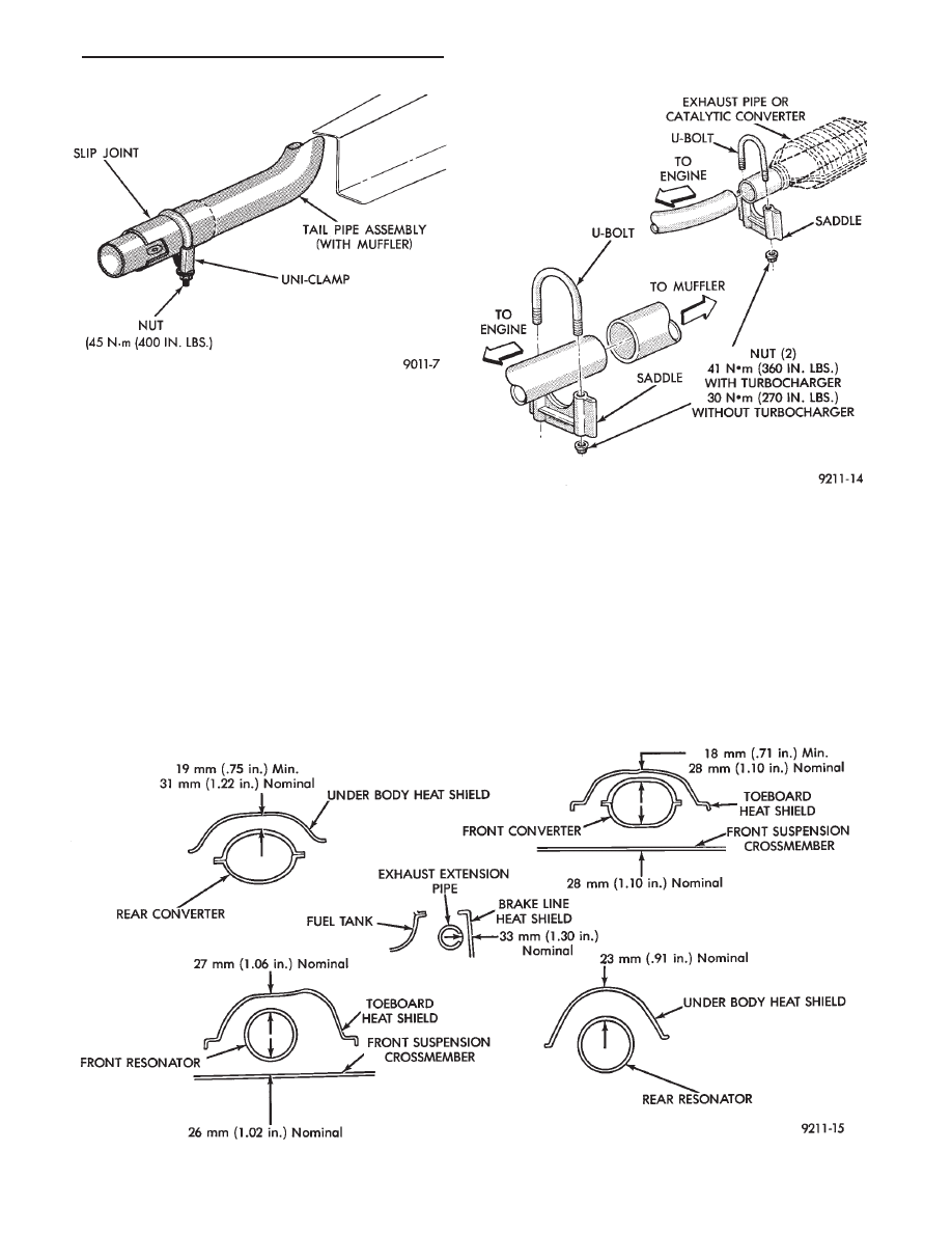
EXHAUST PIPES, MUFFLERS AND TAILPIPES
REMOVAL
(1) Raise vehicle on hoist and apply penetrating oil
to clamp bolts and nuts of component being removed.
(2) Tail pipes are integral with the muffler (Fig. 5).
Remove clamp at slip joint. Separate at slip joint.
(3) Remove clamps and supports (Figs. 6, 7, 8, and 9)
from exhaust system to permit alignment of parts
during assembly.
(4) When removing tailpipe, raise rear of vehicle to
relieve body weight from rear springs to provide clear-
ance between pipe and rear axle parts.
(5) Clean ends of pipes and/or muffler to assure
mating of all parts. Discard broken or worn insulators,
rusted clamps, supports and attaching parts.
When replacement is required on any compo-
nent of the exhaust system, it is most important
that original equipment parts (or their equiva-
lent) be used;
• To insure proper alignment with other parts in the
system.
• Provide acceptable exhaust noise levels and does not
change exhaust system back pressure that could affect
emissions and performance.
INSTALLATION
(1) Assemble ball joint connection pipes, supports
and clamps loosely to permit alignment of all parts.
Fig. 6 Insulator Tail Pipe and Muffler Support
Fig. 7 Underfloor Converter or Extension Pipe
Support—2 Places
Fig. 5 Tail Pipe with Muffler—Typical
11 - 4
EXHAUST SYSTEM AND INTAKE MANIFOLD
Ä
(2) Beginning at the ball joint, align and torque
shoulder bolts (Fig. 3).
(3) Working from the front of system, align and
clamp each component to maintain position and
proper clearance with underbody parts (Fig. 10).
(4) Tighten all clamps and supports to the proper
torques and clearances.
INTAKE AND EXHAUST MANIFOLDS—TBI ENGINE
INTAKE MANIFOLD
Naturally Aspirated Die-cast aluminum long-
branch fan design with remote plenum. The throttle
body is installed on the upper plenum of the mani-
fold.
EXHAUST MANIFOLD
All high strength iron casting that intermesh with
the intake manifold. For standard engines a four
branch design collects and directs exhaust gases to
the conical (articulated joint connection) outlet.
THROTTLE BODY AIR HEATER
The throttle body air heater (Fig. 1) is attached to
the exhaust manifold and is removable.
Inspect air heater connector tube; replace if dam-
aged. Refer to Emission Control Systems Group 25,
Fig. 9 First Slip Joint Connection
Fig. 10 Exhaust Clearance
Fig. 8 Front Tail Pipe Uni-Clamp
Ä
EXHAUST SYSTEM AND INTAKE MANIFOLD
11 - 5
Нет комментариевНе стесняйтесь поделиться с нами вашим ценным мнением.
Текст