Infiniti FX35 / FX45. Manual — part 304

LANE DEPARTURE WARNING SYSTEM
DI-91
< SERVICE INFORMATION >
C
D
E
F
G
H
I
J
L
M
A
B
DI
N
O
P
Turn Signal Input Inspection
INFOID:0000000001328513
1.
CHECK TURN SIGNAL INPUT
Check turn signal input “TURN SIGNAL” in “Data Monitor” mode with CONSULT-III.
OK or NG
OK
>> INSPECTION END
NG
>> Check turn signal and hazard warning lamps system, and repair or replace corresponding parts.
LT-88, "How to Proceed with Trouble Diagnosis"
Electrical Component Inspection
INFOID:0000000001328514
LDW SWITCH
Check continuity between terminals 6 and 7.
Removal and Installation for LDW Camera Unit
INFOID:0000000001328515
REMOVAL
1.
2.
Disconnect LDW camera unit connector.
3.
Remove the bolts (3), and remove LDW camera unit.
INSTALLATION
Installation is the reverse order of removal.
CAUTION:
• Remove the camera lens cap for replacement.
• Never give an impact to the LDW camera unit.
• Adjust the camera aiming every time the LDW camera unit is removed or installed. Refer to
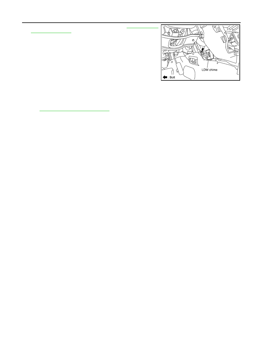
Removal and Installation for LDW Chime
INFOID:0000000001328516
REMOVAL
“TURN SIGNAL”
When lighting switch is in TURN RH position
: RH
When lighting switch is in TURN LH position
: LH
When hazard switch is turned ON
: RH/LH
Terminal
Condition
Continuity
6
7
When LDW switch is pressed.
Yes
When LDW switch is released.
No
PKIB4704E
SKIB1791E
DI-92
< SERVICE INFORMATION >
LANE DEPARTURE WARNING SYSTEM
1.
Remove instrument side panel (LH). Refer to
2.
Remove the bolt (1).
3.
Disconnect LDW chime connector and remove LDW chime.
INSTALLATION
Installation is the reverse order of removal.
Removal and Installation for LDW Switch
INFOID:0000000001328517
IP-10, "Component Parts Location"
SKIB1802E
CAN COMMUNICATION
DI-93
< SERVICE INFORMATION >
C
D
E
F
G
H
I
J
L
M
A
B
DI
N
O
P
CAN COMMUNICATION
System Description
INFOID:0000000001328518
CAN (Controller Area Network) is a serial communication line for real time application. It is an on-vehicle mul-
tiplex communication line with high data communication speed and excellent error detection ability. Many elec-
tronic control units are equipped onto a vehicle, and each control unit shares information and links with other
control units during operation (not independent). In CAN communication, control units are connected with 2
communication lines (CAN-H line, CAN-L line) allowing a high rate of information transmission with less wiring.
Each control unit transmits/receives data but selectively reads required data only.
CAN Communication Unit
INFOID:0000000001328519
LAN-43, "CAN System Specification Chart"
in “LAN SYSTEM”.
DI-94
< SERVICE INFORMATION >
COMPASS
COMPASS
Precaution for Compass
INFOID:0000000001328520
NOTE:
• Do not install the ski rack, antenna, etc. which is attach to the vehicle with a magnet base. It affects the oper-
ation of the compass.
• When cleaning the mirror, use a paper towel or similar material dampened with glass cleaner. Do not spray
glass cleaner directly on the mirror as it may cause the liquid cleaner to enter the mirror housing.
System Description
INFOID:0000000001328521
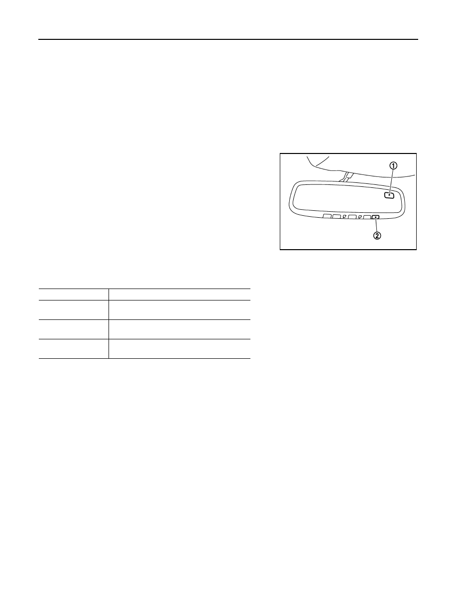
• This electronic compass is able to display 8 primary directions: N, NE, E, SE, S, SW, W, NW.
• The inside mirror switch (2) is used to operate the compass and
automatic anti-glare system.
Switch Operation
NOTE:
For further details of the compass and automatic anti-glare system, refer to Owner's Manual
• All standard compasses determine direction relative to Magnetic North; however, this electronic compass is
designed to display direction relative to True North.
• The difference between Magnetic North and True North varies from place to place across the surface of the
earth.
• This electronic compass must be “told” approximately where it is on the earth’s surface so that the Magnetic
North reading can be properly converted into a True North display.
• To tell the electronic compass where it’s at, the earth is separated into numbered “Zone Variances”. The
Zone Variance number in which the compass is to function must be entered into this electronic compass.
• Each zone is magnetically about 4.2
°
wide. Typically, anything under 22.5
°
total zone change is not noticed
on the electronic compass display. However, over 22.5
°
, a reading may be off by one or more primary direc-
tions.
• On long trips, a vehicle may leave its original zone and enter one or more new zones. Generally, you do not
need to reset the compass zone if you travel between 3 or 4 zones, such as business travel or vacation. The
typical driver will not notice any difference on the display within 3 or 4 zones. However, if the vehicle is “per-
manently” moved to a new location, it is recommended that the compass zone be reset.
Troubleshooting
INFOID:0000000001328522
• The electronic compass is highly protected from changes in most magnetic fields. However, some large
changes in magnetic fields can affect it. Some examples are (but not limited to): high tension power lines,
large steel buildings, subways, steel bridges, automatic car washes, large piles of scrap metal, etc. While
this does not happen very often, it is possible.
1.
Compass display
2.
Inside mirror switch
SKIB8487E
Press
Compass is turned ON/OFF
Press and hold
(for 3 – 6 sec.)
Automatic anti-glare system turns ON/OFF
Press and hold
(for 6 – 9 sec.)
Compass display turns to zone variation change
mode
Press and hold
(for more than 9 sec.)
Compass display turns to calibration mode
Нет комментариевНе стесняйтесь поделиться с нами вашим ценным мнением.
Текст