Infiniti FX35 / FX45. Manual — part 303
LANE DEPARTURE WARNING SYSTEM
DI-87
< SERVICE INFORMATION >
C
D
E
F
G
H
I
J
L
M
A
B
DI
N
O
P
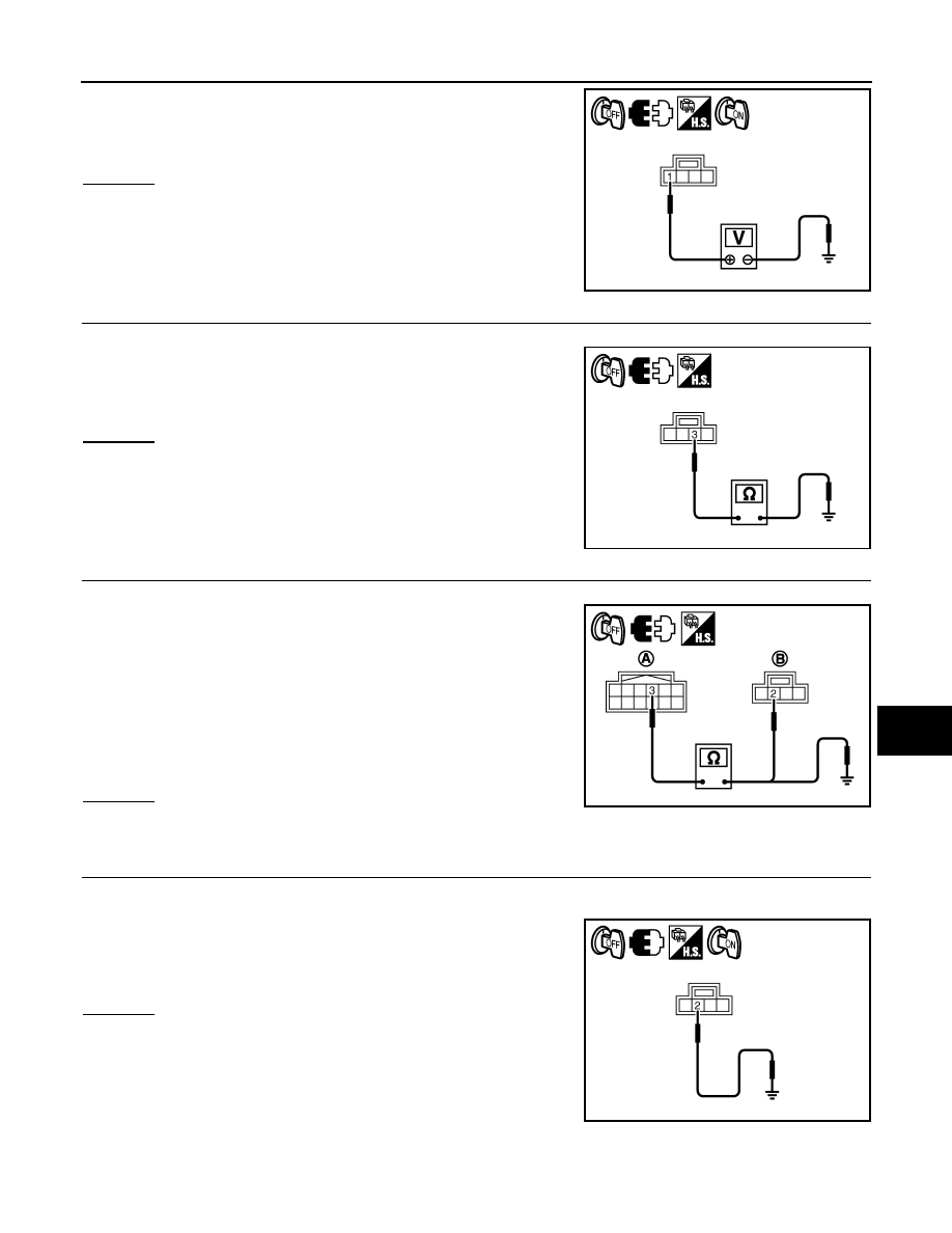
4.
Check voltage between warning chime harness connector M97
terminal 1 and ground.
OK or NG
OK
>> GO TO 3.
NG
>> Check harness between fuse and LDW chime.
3.
CHECK LDW CHIME GROUND CIRCUIT
1.
Turn ignition switch OFF.
2.
Check continuity between LDW chime harness connector M97
terminal 3 and ground.
OK or NG
OK
>> GO TO 4.
NG
>> Repair harness or connector.
4.
CHECK LDW CHIME SIGNAL CIRCUIT
1.
Disconnect LDW camera unit connector.
2.
Check continuity between LDW camera unit harness connector
(A) R9 terminal 3 and LDW chime harness connector (B) M97
terminal 2.
3.
Check continuity between LDW camera unit harness connector
(A) R9 terminal 3 and ground.
OK or NG
OK
>> GO TO 5.
NG
>> Repair harness or connector.
5.
CHECK LDW CHIME OPERATION
1.
Connect LDW chime connector.
2.
Turn ignition switch ON.
3.
Apply ground to LDW chime terminal 2.
4.
Check condition of the LDW chime.
OK or NG
OK
>> Replace LDW camera unit.
NG
>> Replace LDW chime.
1 – Ground
: Battery voltage
PKIC0248E
3 – Ground
: Continuity should exist.
PKIC0249E
3 – 2
: Continuity should exist.
3 – Ground
: Continuity should not exist.
SKIB8694E
2 – Ground
: LDW chime should operate.
PKIC0251E
DI-88
< SERVICE INFORMATION >
LANE DEPARTURE WARNING SYSTEM
LDW Switch Circuit Inspection
INFOID:0000000001328511
1.
CHECK OPERATION OF LDW SYSTEM ON INDICATOR
1.
Turn ignition switch ON.
2.
Check LDW system ON indicator operation when LDW switch is ON/OFF.
OK or NG
OK
>> INSPECTION END
NG
>> GO TO 2.
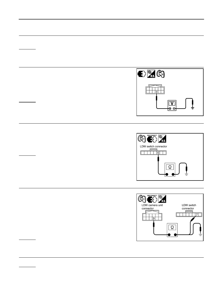
2.
CHECK LDW SWITCH SIGNAL INPUT
Check voltage between LDW camera unit harness connector R9 ter-
minal 9 and ground.
OK or NG
OK
>> GO TO 6.
NG
>> GO TO 3.
3.
CHECK LDW SWITCH GROUND CIRCUIT
1.
Turn ignition switch OFF.
2.
Disconnect LDW switch connector.
3.
Check continuity between LDW switch connector M96 terminal 6
and ground.
OK or NG
OK
>> GO TO 4.
NG
>> Repair harness or connector.
4.
CHECK LDW SWITCH SIGNAL INPUT CIRCUIT
1.
Disconnect LDW camera unit connector.
2.
Check continuity between LDW camera unit harness connector
R9 terminal 9 and LDW switch harness connector M96 terminal
7.
3.
Check continuity between LDW camera unit harness connector
R9 terminal 9 and ground.
OK or NG
OK
>> GO TO 5.
NG
>> Repair harness or connector.
5.
CHECK LDW SWITCH
Check LDW switch. Refer to
OK or NG
OK
>> Replace LDW camera unit.
NG
>> Replace LDW switch.
9 – Ground
When LDW switch is pressed
: Approx. 0 V
When LDW switch is released
: Approx. 5 V
PKIC0252E
6 – Ground
: Continuity should exist.
PKIB4702E
9 – 7
: Continuity should exist.
9 – Ground
: Continuity should not exist.
PKIB4703E
LANE DEPARTURE WARNING SYSTEM
DI-89
< SERVICE INFORMATION >
C
D
E
F
G
H
I
J
L
M
A
B
DI
N
O
P
6.
CHECK OPERATION OF LDW SYSTEM ON INDICATOR
Check LDW system ON indicator operation “SYSTEM ON LAMP DRIVE” in “Active Test” mode with CON-
SULT-III.
NOTE:
Perform “SYSTEM ON LAMP DRIVE” when LDW system ON indicator turns OFF.
OK or NG
OK
>> Replace LDW camera unit.
NG
>> GO TO 7.
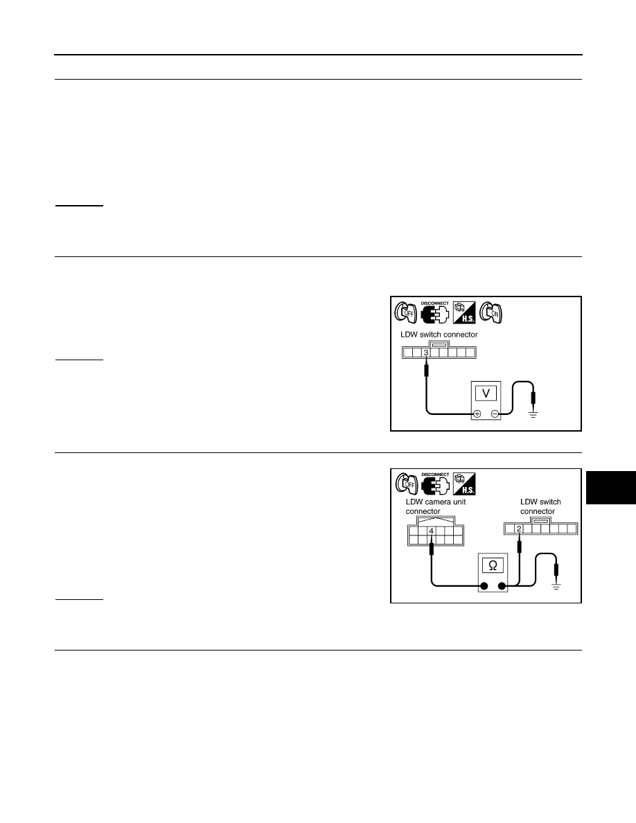
7.
CHECK LDW SYSTEM ON INDICATOR POWER SUPPLY CIRCUIT
1.
Turn ignition switch OFF.
2.
Disconnect LDW switch connector.
3.
Turn ignition switch ON.
4.
Check voltage between LDW switch harness connector M96 ter-
minal 3 and ground.
OK or NG
OK
>> GO TO 8.
NG
>> Check harness between fuse and LDW switch.
8.
CHECK LDW SYSTEM ON INDICATOR SIGNAL CIRCUIT
1.
Disconnect LDW camera unit connector.
2.
Check continuity between LDW camera unit harness connector
R9 terminal 4 and LDW switch harness connector M96 terminal
2.
3.
Check continuity between LDW camera unit harness connector
R9 terminal 4 and ground.
OK or NG
OK
>> GO TO 9.
NG
>> Repair harness or connector.
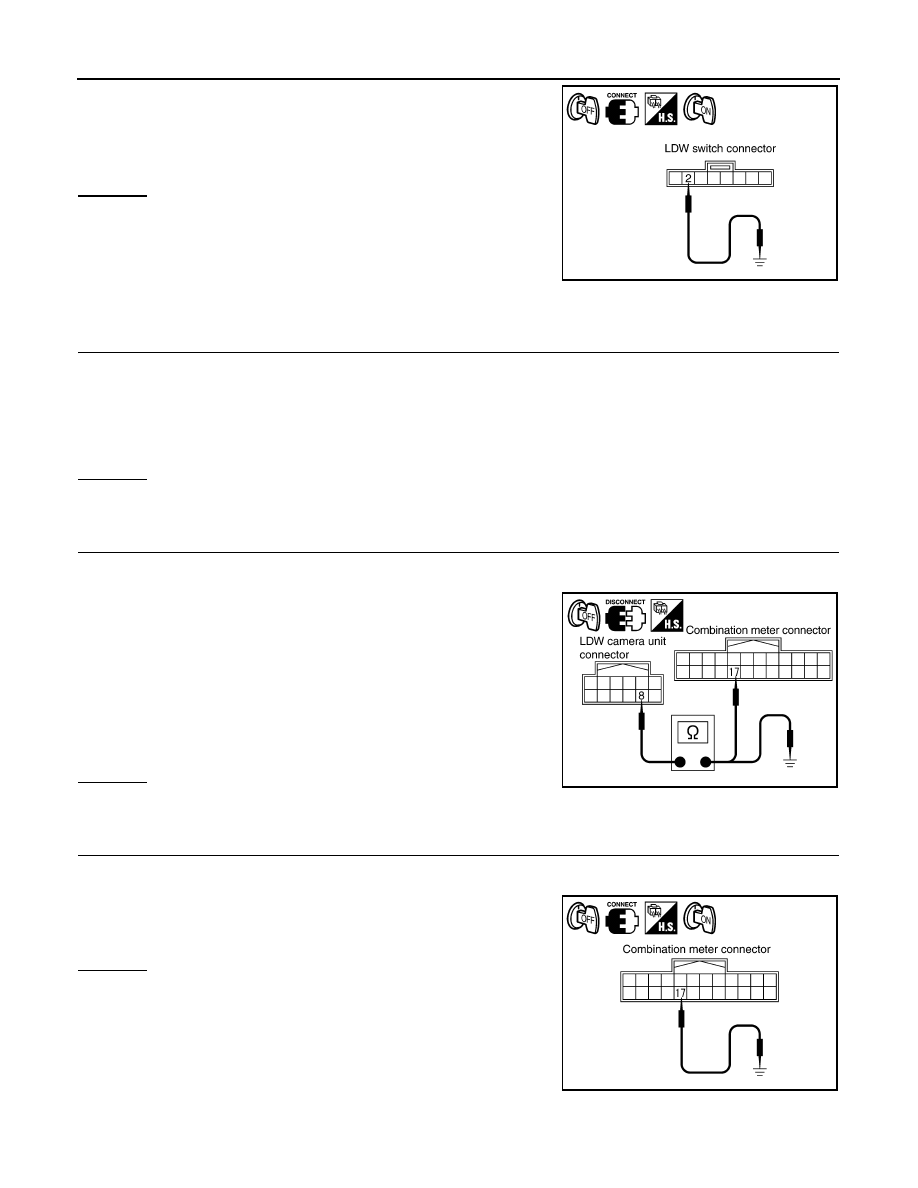
9.
CHECK LDW SYSTEM ON INDICATOR
1.
Connect LDW switch connector.
2.
Turn ignition switch ON.
“SYSTEM ON LAMP DRIVE”
Select “On”
: LDW system ON indicator illuminates.
Select “Off”
: LDW system ON indicator turns OFF.
3 – Ground
: Battery voltage
PKIB4705E
4 – 2
: Continuity should exist.
4 – Ground
: Continuity should not exist.
PKIB4706E
DI-90
< SERVICE INFORMATION >
LANE DEPARTURE WARNING SYSTEM
3.
Apply ground to LDW switch terminal 2.
4.
Check condition of the LDW system ON indicator.
OK or NG
OK
>> Replace LDW camera unit.
NG
>> Replace LDW switch.
LDW Indicator Lamp Circuit Inspection
INFOID:0000000001328512
1.
CHECK OPERATION OF LDW INDICATOR LAMP
Check LDW indicator operation “INDICATOR LAMP DRIVE” in “Active Test” mode with CONSULT-III.
OK or NG
OK
>> INSPECTION END
NG
>> GO TO 2.
2.
CHECK LDW INDICATOR LAMP SIGNAL CIRCUIT
1.
Turn ignition switch OFF.
2.
Disconnect LDW camera unit connector and combination meter connector.
3.
Check continuity between LDW camera unit harness connector
R9 terminal 8 and combination meter harness connector M20
terminal 17.
4.
Check continuity between LDW camera unit harness connector
R9 terminal 8 and ground.
OK or NG
OK
>> GO TO 3.
NG
>> Repair harness or connector.
3.
CHECK LDW INDICATOR LAMP OPERATION
1.
Connect combination meter connector.
2.
Turn ignition switch ON.
3.
Ground combination meter harness connector M20 terminal 17.
OK or NG
OK
>> Replace LDW camera unit.
NG
>> Replace combination meter.
2 – Ground
: LDW system ON indicator
should illuminate.
PKIB4707E
“INDICATOR LAMP DRIVE”
Select “On”
: LDW indicator lamp illuminates.
Select “Off”
: LDW indicator lamp OFF.
8 – 17
: Continuity should exist.
8 – Ground
: Continuity should not exist.
PKIB4708E
17 – Ground
: LDW indicator should illuminate.
PKIB4709E
Нет комментариевНе стесняйтесь поделиться с нами вашим ценным мнением.
Текст