Infiniti FX35 / FX45. Manual — part 192
POWER DOOR LOCK SYSTEM
BL-35
< SERVICE INFORMATION >
C
D
E
F
G
H
J
K
L
M
A
B
BL
N
O
P
Terminal and Reference Value for BCM
INFOID:0000000001327797
Terminal and Reference Value for Intelligent Key Unit (With Intelligent Key System)
INFOID:0000000001327798
Termi-
nal
Wire
Color
Item
Signal
Input/
output
Condition
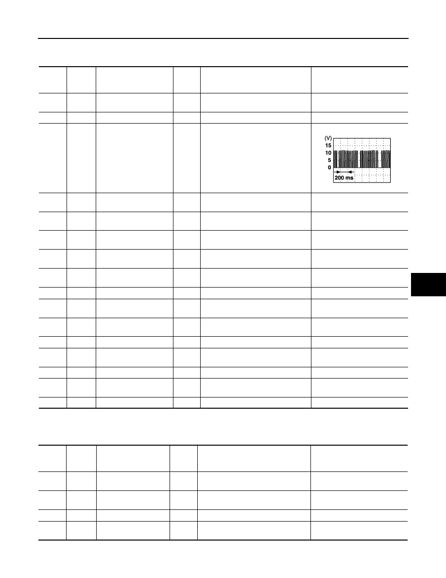
Voltage (V)
(Approx.)
12
P/B
Front door switch (Pas-
senger side)
Input
ON (door open)
→
OFF (door closed)
0
→
Battery voltage
13
P/L
Rear door switch RH
Input
ON (door open)
→
OFF (door closed)
0
→
Battery voltage
22
OR
Power window serial link
Input/
Output
Ignition switch ON
37
B/W
Key switch
Input
ON (Key inserted)
→
OFF (Key re-
moved from IGN key cylinder)
Battery voltage
→
0
39
L
CAN H
Input/
Output
—
—
40
P
CAN L
Input/
Output
—
—
42
L/R
Battery power supply
(fuse)
Input
—
Battery voltage
44
Y
Driver door lock actuator
(unlock)
Output
Door lock / unlock switch
(Free
→
Unlock)
0
→
Battery voltage
→
0
49
B
Ground
—
—
0
50
PU
Door lock actuator (lock)
Output
Door lock / unlock switch
(Free
→
Lock)
0
→
Battery voltage
→
0
51
W/B
Passenger and rear doors
lock actuator (unlock)
Output
Door lock / unlock switch
(Free
→
Unlock)
0
→
Battery voltage
→
0
52
B
Ground
—
—
0
55
G
Power source (Fusible
link)
Input
—
Battery voltage
58
L
Back door switch
Input
ON (Door open)
→
OFF (Door closed)
0
→
9
62
W
Front door switch (Driver
side)
Input
ON (Door open)
→
OFF (Door closed)
0
→
Battery voltage
63
P
Rear door switch LH
Input
ON (Door open)
→
OFF (Door closed)
0
→
Battery voltage
PIIA2344J
Termi-
nal
Wire
Color
Item
Signal
Input/
output
Condition
Voltage (V)
(Approx.)
2
L
CAN H
Input/
Output
—
—
3
P
CAN L
Input/
Output
—
—
27
L/W
Push switch
Input
Push switch (OFF
→
ON)
0
→
Battery voltage
40
BR/W
AS unlock output signal
Output
Door lock / unlock switch
(Free
→
Unlock)
0
→
Battery voltage

BL-36
< SERVICE INFORMATION >
POWER DOOR LOCK SYSTEM
Work Flow
INFOID:0000000001327799
1.
Check the symptom and customer's requests.
2.
Understand the outline of system. Refer to
.
3.
According to the trouble diagnosis chart by symptom, repair or replace the cause of the malfunction.
Refer to
BL-37, "Trouble Diagnosis Chart by Symptom"
.
4.
Does power door lock system operate normally?
YES: GO TO 5.
NO: GO TO 3.
5.
INSPECTION END
CONSULT-III Function (BCM)
INFOID:0000000001327800
CONSULT-III APPLICATION ITEMS
Work Support
Data Monitor
*: With Intelligent Key system
Active Test
BCM diagnosis
test item
Check item diagnosis test mode
Content
Door lock
DATA MONITOR
Displays the input data of BCM real time.
ACTIVE TEST
Gives a drive signal to a load to check the operation.
Work item
Description
DOOR LOCK-UNLOCK SET
Select unlock mode can be changed in this mode. Selects ON-OFF of select unlock mode.
ANTI-LOCK OUT SET
Key reminder door mode can be changed in this mode. Selects ON-OFF of key reminder door
mode.
Monitor item
Content
IGN ON SW
Indicates [ON/OFF] condition of ignition switch in ON position.
KEY ON SW
Indicates [ON/OFF] condition of key switch.
CDL LOCK SW
Indicates [ON/OFF] condition of lock signal from door lock and unlock switch.
CDL UNLOCK SW
Indicates [ON/OFF] condition of unlock signal from door lock and unlock switch.
DOOR SW-DR
Indicates [ON/OFF] condition of front door switch driver side.
DOOR SW-AS
Indicates [ON/OFF] condition of front door switch passenger side.
DOOR SW-RR
Indicates [ON/OFF] condition of rear door switch RH.
DOOR SW-RL
Indicates [ON/OFF] condition of rear door switch LH.
BACK DOOR SW
Indicates [ON/OFF] condition of back door switch.
KEY CYL LK-SW
Indicates [ON/OFF] condition of lock signal from key cylinder.
KEY CYL UN-SW
Indicates [ON/OFF] condition of unlock signal from key cylinder.
KEYLESS LOCK
Indicates [ON/OFF] condition of lock signal from key fob.
KEYLESS UNLOCK
Indicates [ON/OFF] condition of unlock signal from key fob.
I-KEY LOCK*
Indicates [ON/OFF] condition of lock signal from door request switch.
I-KEY UNLOCK*
Indicates [ON/OFF] condition of unlock signal from door request switch.
POWER DOOR LOCK SYSTEM
BL-37
< SERVICE INFORMATION >
C
D
E
F
G
H
J
K
L
M
A
B
BL
N
O
P
Trouble Diagnosis Chart by Symptom
INFOID:0000000001327801
Always check the “Work Flow” before troubleshooting. Refer to
.
*
1
: Lock operation
*
2
: Unlock operation
*
3
: Driver side
*
4
: Except driver side
Check BCM Power Supply and Ground Circuit
INFOID:0000000001327802
1.
CHECK FUSE AND FUSIBLE LINK
• Check 50A fusible link (letter M, located in the fuse and fusible link box).
• Check 15A fuse [No. 22, located in the fuse block (J/B)].
Test item in “DOOR LOCK”
Content
ALL LOCK
This test is able to check all door lock actuators lock operation.
These actuators lock when “ALL LOCK” on CONSULT-III screen is touched.
ALL UNLOCK
This test is able to check all door lock actuators unlock operation.
These actuators unlock when “ALL UNLOCK” on CONSULT-III screen is touched.
DR UNLOCK
This test is able to check door lock actuator (driver side) unlock operation.
This actuator unlock when “DR UNLOCK” on CONSULT-III screen is touched.
OTHER UNLOCK
This test is able to check all door lock actuators (except driver side) unlock operation.
These actuators unlock when “OTHER UNLOCK” on CONSULT-III screen is touched.
Symptom
Diagnoses service procedure
Reference
page
Key reminder door system does not operate properly.
1.Check key reminder door mode.*
*: Key reminder door mode can be changed.
First check key reminder door mode.
2. Check BCM power supply and ground cir-
cuit
3. Check key switch.
4. Check door switch.
5. Replace BCM.
Power door lock does not operate with door lock and unlock switch.
2. Check BCM power supply and ground cir-
cuit
2. Check door lock and unlock switch.
3. Replace BCM.
Power door lock does not operate with door key cylinder operation.
(Power door lock operate properly with door lock and unlock switch.)
1. Check front door key cylinder switch.
1
2
2. Replace power window main switch.
–
Specific door lock actuator does not operate.
1. Check door lock actuator.
3
4
2. Replace BCM.
Rear door lock actuator (LH and RH) does not operate.*
*: Only model with intelligent key system.
1. Check select unlock relay circuit.
Select unlock does not operate.
(All other power door lock system is “OK”.)
1. Check select unlock mode.*
*: Select unlock mode can be changed.
First check select unlock mode.
2. Replace BCM.
Fuel lid lock actuator does not operate.
(All door lock actuators operates properly.)
1.Check fuel lid lock actuator.
BL-38
< SERVICE INFORMATION >
POWER DOOR LOCK SYSTEM
NOTE:
Refer to
BL-21, "Component Parts and Harness Connector Location"
.
OK or NG
OK
>> GO TO 2.
NG
>> If fuse is blown, be sure to eliminate cause of malfunction before installing new fuse, refer to
2.
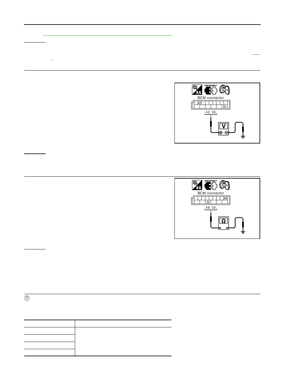
CHECK POWER SUPPLY CIRCUIT
1.
Turn ignition switch OFF.
2.
Disconnect BCM connectors.
3.
Check voltage between BCM connectors M4 terminals 42, 55
and ground.
OK or NG
OK
>> GO TO 3.
NG
>> Repair or replace BCM power supply circuit.
3.
CHECK GROUND CIRCUIT
Check continuity between BCM connectors M4 terminals 49, 52 and
ground.
OK or NG
OK
>> Power supply and ground circuit are OK.
NG
>> Repair or replace BCM ground circuit.
Check Door Switch
INFOID:0000000001327803
CHECK DOOR SWITCH (EXCEPT BACK DOOR SWITCH)
1.
CHECK DOOR SWITCH INPUT SIGNAL
With CONSULT-III
Check door switches (“DOOR SW-DR”, “DOOR SW-AS”, “DOOR SW-RL” and “DOOR SW-RR”) in “DATA
MONITOR” mode with CONSULT-III.
42 (L/R) – Ground
: Battery voltage
55 (G) – Ground
: Battery voltage
PIIA6374E
49 (B) – Ground
: Continuity should exist.
52 (B) – Ground
: Continuity should exist.
PIIA6375E
Monitor item
Condition
DOOR SW-DR
CLOSE
→
OFF
OPEN
→
ON
DOOR SW-AS
DOOR SW-RL
DOOR SW-RR
Нет комментариевНе стесняйтесь поделиться с нами вашим ценным мнением.
Текст