Infiniti FX35 / FX45. Manual — part 193
POWER DOOR LOCK SYSTEM
BL-39
< SERVICE INFORMATION >
C
D
E
F
G
H
J
K
L
M
A
B
BL
N
O
P
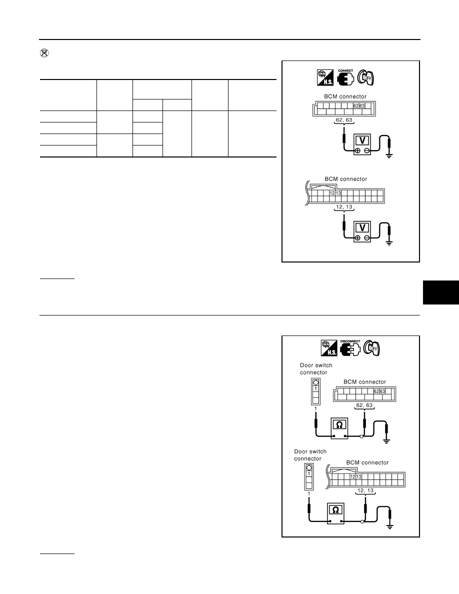
Without CONSULT-III
Check voltage between BCM connector and ground.
OK or NG
OK
>> Door switch circuit is OK.
NG
>> GO TO 2.
2.
CHECK DOOR SWITCH CIRCUIT
1.
Turn ignition switch OFF.
2.
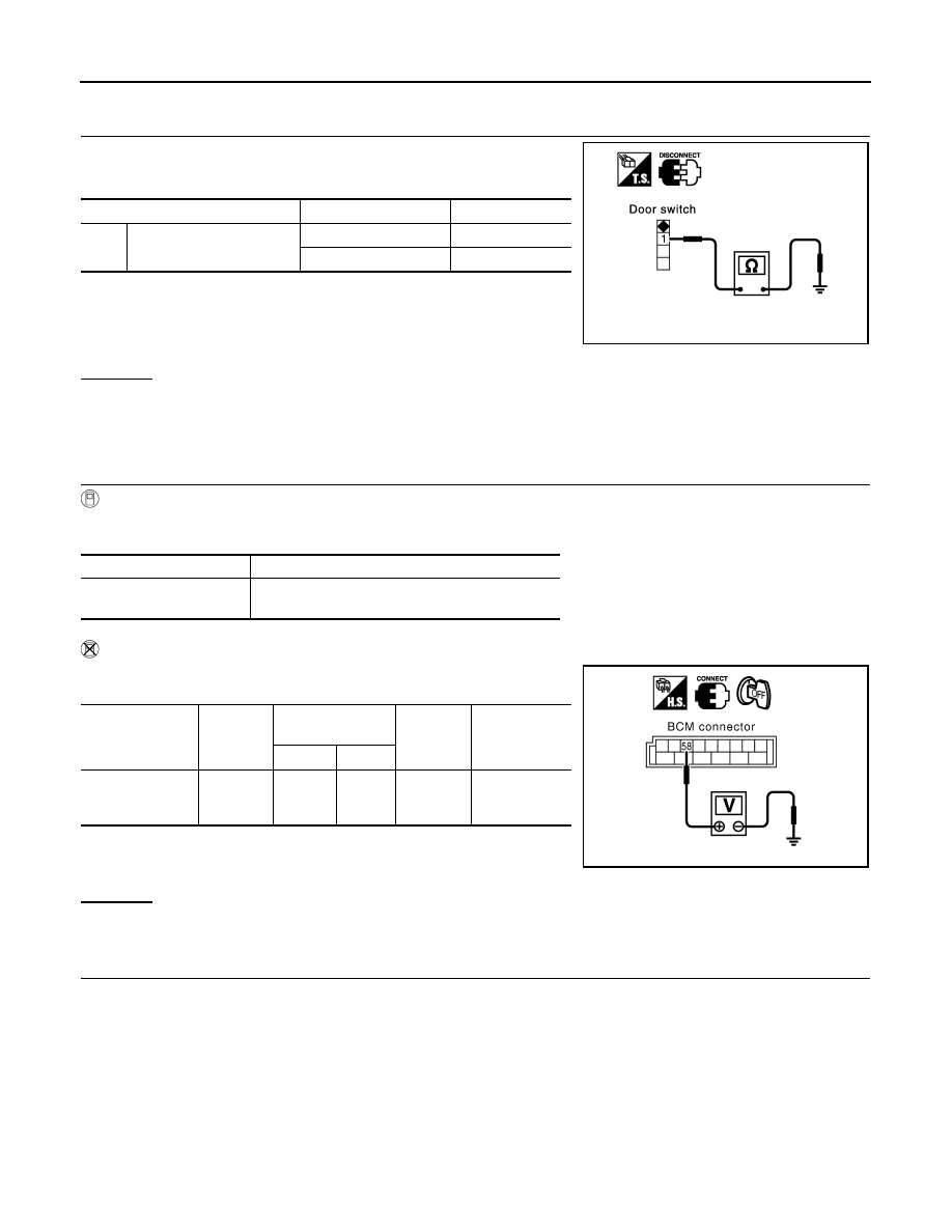
Disconnect door switch and BCM connector.
3.
Check continuity between door switch connector B26, B36, B46,
B206 terminals 1 and BCM connector M3, B14 terminals 62, 12,
63, 13.
4.
Check continuity between door switch connector B26, B36, B46,
B206 terminal 1 and ground.
OK or NG
OK
>> GO TO 3.
Item
Connector
Terminals
(Wire color)
Door
condition
Voltage (V)
(Approx.)
(+)
(-)
Driver side
B14
62 (W)
Ground
CLOSE
↓
OPEN
Battery voltage
↓
0
Rear LH
63 (P)
Passenger side
M3
12 (P/B)
Rear RH
13 (P/L)
PIIA7003E
Driver side door
1 (W) – 62 (W)
: Continuity should exist.
Passenger side door
1 (SB) – 12 (P/B)
: Continuity should exist.
Rear door LH
1 (P) – 63 (P)
: Continuity should exist.
Rear door RH
1 (P) – 13 (P/L)
: Continuity should exist.
1 (W, SB, P) – Ground
: Continuity should not exist.
PIIA7004E
BL-40
< SERVICE INFORMATION >
POWER DOOR LOCK SYSTEM
NG
>> Repair or replace harness.
3.
CHECK DOOR SWITCH
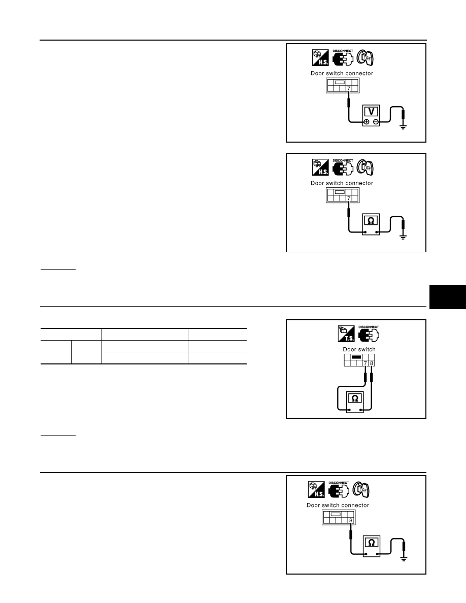
Check continuity between door switch terminal 1 and ground part of
door switch.
OK or NG
OK
>> Check door switch case ground condition.
NG
>> Replace door switch.
CHECK BACK DOOR SWITCH
1.
CHECK BACK DOOR SWITCH INPUT SIGNAL
With CONSULT-III
Check door switches (“BACK DOOR SW”) in “DATA MONITOR” mode with CONSULT-III.
Without CONSULT-III
Check voltage between BCM connector and ground.
OK or NG
OK
>> Door switch circuit is OK.
NG
>> GO TO 2.
2.
CHECK BACK DOOR SWITCH CIRCUIT
1.
Turn ignition switch OFF.
2.
Disconnect back door switch connector.
Terminal
Door switch condition
Continuity
1
Ground part of door switch
Pushed
No
Released
Yes
PIIA3351E
Monitor item
Condition
BACK DOOR SW
CLOSE
→
OFF
OPEN
→
ON
Item
Connector
Terminal
(Wire color)
Back door
condition
Voltage (V)
(Approx.)
(+)
(-)
Back door switch
B14
58 (L)
Ground
CLOSE
↓
OPEN
9
↓
0
PIIA6473E
POWER DOOR LOCK SYSTEM
BL-41
< SERVICE INFORMATION >
C
D
E
F
G
H
J
K
L
M
A
B
BL
N
O
P
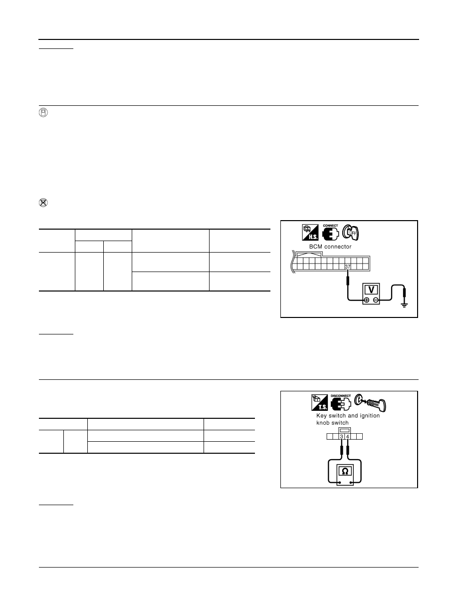
3.
Check voltage between back door switch connector D109 termi-
nal 7 and ground. (Check harness for open.)
4.
Check continuity between back door switch connector D109 ter-
minal 7 and ground. (Check harness for short.)
OK or NG
OK
>> GO TO 3.
NG
>> Repair or replace harness.
3.
CHECK BACK DOOR SWITCH
Check continuity between back door switch terminals 7 and 8.
OK or NG
OK
>> GO TO 4.
NG
>> Replace back door closure motor (door switch).
4.
CHECK BACK DOOR SWITCH GROUND HARNESS
Check continuity between back door switch connector D109 terminal
8 and ground.
7 (L) – Ground
: Approx. 9V
PIIA6474E
7 (L) – Ground
: Continuity should not exist.
PIIA6475E
Terminal
Back door condition
Continuity
7
8
Closed
No
Opened
Yes
PIIA6476E
8 (B) – Ground
: Continuity should exist.
PIIA6477E
BL-42
< SERVICE INFORMATION >
POWER DOOR LOCK SYSTEM
OK or NG
OK
>> Check harness connection.
NG
>> Repair or replace harness.
Check Key Switch
INFOID:0000000001327804
1.
CHECK KEY SWITCH INPUT SIGNAL
With CONSULT-III
Check ignition key switch “KEY ON SW” in “DATA MONITOR” mode with CONSULT-III.
• When key is inserted in ignition key cylinder
• When key is removed from ignition key cylinder
Without CONSULT-III
Check voltage between BCM connector and ground.
OK or NG
OK
>> Key switch circuit is OK.
NG
>> GO TO 2. (With Intelligent Key)
NG
>> GO TO 3. (Without Intelligent Key)
2.
CHECK KEY SWITCH (WITH INTELLIGENT KEY)
1.
Disconnect key switch and ignition knob switch connector.
2.
Check continuity between key switch or key switch and ignition
knob switch terminals 3 and 4.
OK or NG
OK
>>
Check the following.
• 15A fuse (No. 22, located in fuse and fusible link block)
• Harness for open or short between key switch and fuse
• Harness for open or short between BCM and key switch
NG
>> Replace key switch or key switch and ignition knob switch.
3.
CHECK KEY SWITCH (WITHOUT INTELLIGENT KEY)
KEY ON SW
: ON
KEY ON SW
: OFF
Connector
Terminal
Condition of key switch
Voltage (V)
Approx.
(+)
(-)
M3
37
(B/W)
Ground
Key is inserted in IGN
key cylinder.
Battery voltage
Key is removed from IGN
key cylinder.
0
PIIA6378E
Terminal
Condition of key switch
Continuity
3
4
Key is inserted in IGN key cylinder.
Yes
Key is removed from IGN key cylinder.
No
PIIA6140E
Нет комментариевНе стесняйтесь поделиться с нами вашим ценным мнением.
Текст