Infiniti FX35 / FX45. Manual — part 217
FRONT DOOR LOCK
BL-135
< SERVICE INFORMATION >
C
D
E
F
G
H
J
K
L
M
A
B
BL
N
O
P
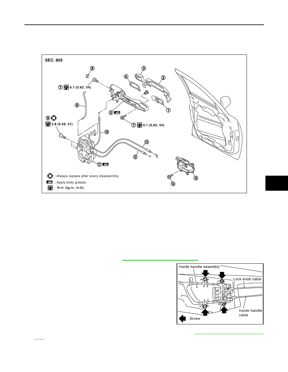
FRONT DOOR LOCK
Removal and Installation
INFOID:0000000001327877
REMOVAL
1.
Remove the front door finisher. Refer to
EI-36, "Component Parts Location"
.
2.
Disconnect the inside handle knob cable and lock knob cable
from the back side of the front door finisher.
3.
Remove the front door glass and front door module assembly. Refer to
4.
Remove door side grommet, and remove door key cylinder assembly (driver side) and outside handle
escutcheon (passenger side) TORX bolt from grommet hole.
CAUTION:
1.
Front gasket
2.
Outside handle
3.
Door key cylinder assembly (Driver
side)
Outside handle escutcheon (Pas-
senger side)
4.
Rear gasket
5.
Outside handle bracket
6.
Grommet
7.
TORX bolt
8.
Key cylinder rod (Driver side only)
9.
TORX bolt
10. Outside handle cable
11.
Door lock assembly
12. Inside handle knob cable
13. Lock knob cable
14. Screw
15. Inside handle
PIIA6025E
PIIA4014E
BL-136
< SERVICE INFORMATION >
FRONT DOOR LOCK
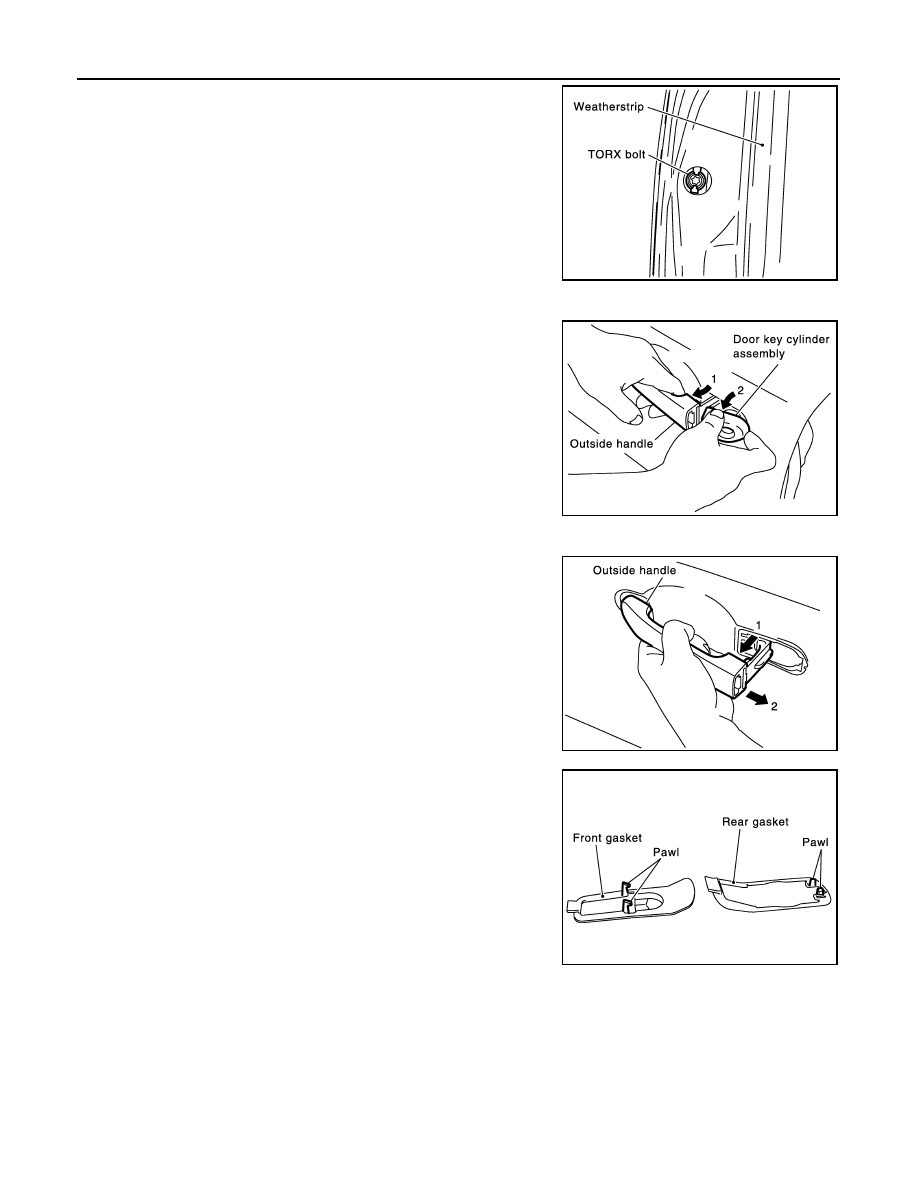
Do not forcibly remove the TORX bolt.
5.
Reach to separate the key cylinder rod connection (on the handle).
6.
While pulling the outside handle, remove door key cylinder
assembly (driver side) and outside handle escutcheon (passen-
ger side).
7.
Disconnect the door request switch connector. (Intelligent Key only)
8.
While pulling outside handle, slide toward rear of vehicle to
remove outside handle.
9.
Remove the front gasket and rear gasket.
PIIA3553E
PIIA3554E
PIIA3555E
PIIA3557E
FRONT DOOR LOCK
BL-137
< SERVICE INFORMATION >
C
D
E
F
G
H
J
K
L
M
A
B
BL
N
O
P
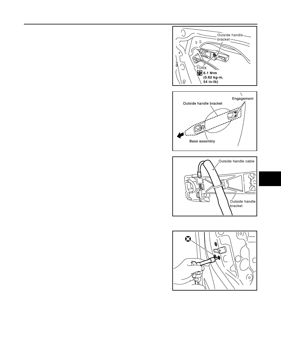
10. Remove the TORX bolt of the outside handle bracket.
11. While pulling outside handle bracket, slide toward front of vehi-
cle to remove outside handle bracket.
12. Reach to separate outside handle cable connection.
13. Remove the TORX bolts of door lock assembly.
14. Disconnect the door lock actuator connector and remove door lock assembly.
INSTALLATION
Install in the reverse order of removal.
CAUTION:
To install each rod, be sure to rotate the rod holder until a click is felt.
PIIA7117E
PIIA3558E
PIIA6026E
PIIB5812E
BL-138
< SERVICE INFORMATION >
REAR DOOR LOCK
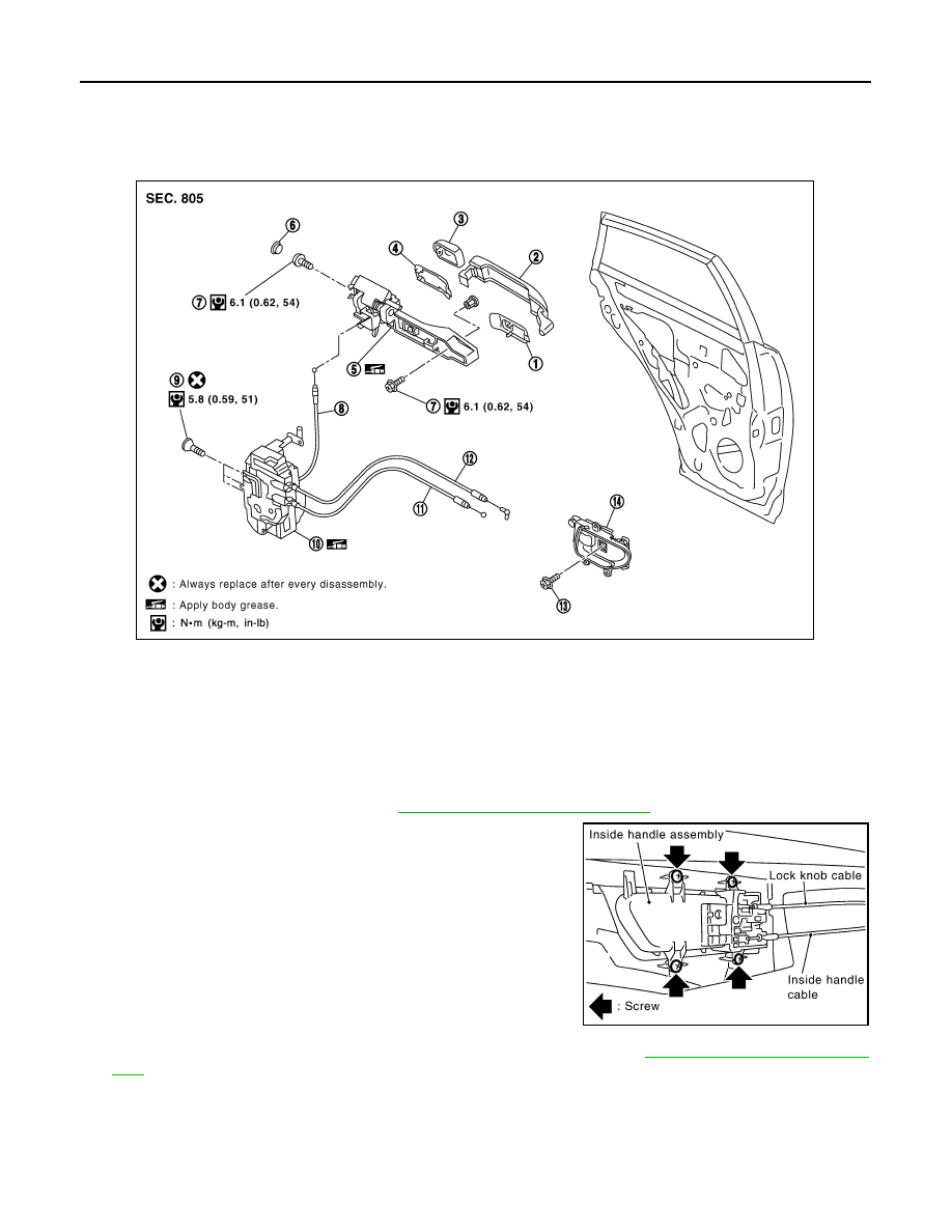
REAR DOOR LOCK
Removal and Installation
INFOID:0000000001327878
REMOVAL
1.
Remove the rear door finisher. Refer to
EI-36, "Component Parts Location"
2.
Disconnect the inside handle knob cable and lock knob cable
from the back side of the front door finisher.
3.
Remove the rear door sealing, glass and corner piece assembly. Refer to
4.
Remove door side grommet, and remove outside handle escutcheon bolt from grommet hole.
CAUTION:
1.
Front gasket
2.
Outside handle
3.
Outside handle escutcheon
4.
Rear gasket
5.
Outside handle bracket
6.
Grommet
7.
TORX bolt
8.
Outside handle cable
9.
TORX bolts
10. Door lock assembly
11.
Inside handle knob cable
12. Lock knob cable
13. Screw
14. Inside handle
PIIA6027E
PIIA4014E
Нет комментариевНе стесняйтесь поделиться с нами вашим ценным мнением.
Текст