Infiniti FX35 / FX45. Manual — part 153
AV-66
< SERVICE INFORMATION >
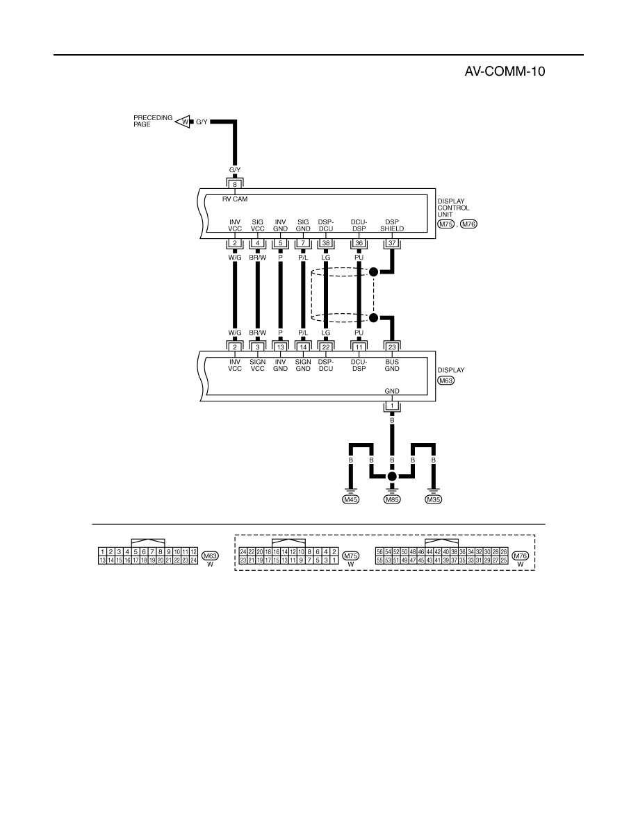
INTEGRATED DISPLAY SYSTEM
TKWM4429E
INTEGRATED DISPLAY SYSTEM
AV-67
< SERVICE INFORMATION >
C
D
E
F
G
H
I
J
L
M
A
B
AV
N
O
P
Terminal and Reference Value for Display Control Unit
INFOID:0000000001328718
Terminal
(Wire color)
Item
Signal
input/
output
Condition
Reference value
+
–
Ignition
switch
Operation
1 (W/L)
Ground
Battery power supply
Input
OFF
—
Battery voltage
2 (W/G)
Ground
Power supply (Invert-
er)
Output
ON
—
Approx. 9 V
3 (B)
Ground
Ground
—
ON
—
Approx. 0 V
4 (BR/W)
Ground
Power supply (Signal)
Output
ON
—
Approx. 9 V
5 (P)
Ground
Ground (Inverter)
—
ON
—
Approx. 0 V
6 (OR)
Ground
Reverse signal
Input
ON
Selector lever in R position
Approx. 12 V
Selector lever except in R
position
Approx. 0 V
7 (P/L)
Ground
Ground (Signal)
—
ON
—
Approx. 0 V
10 (LG)
Ground
ACC power supply
Input
ACC
—
Battery voltage
12 (W)
Ground
Ignition signal
Input
ON
—
Battery voltage
13 (B)
Ground
Ground
—
ON
—
Approx. 0 V
14 (R/L)
Ground
Illumination signal
Input
OFF
Lighting switch ON
Approx. 12 V
Lighting switch OFF
Approx. 0 V
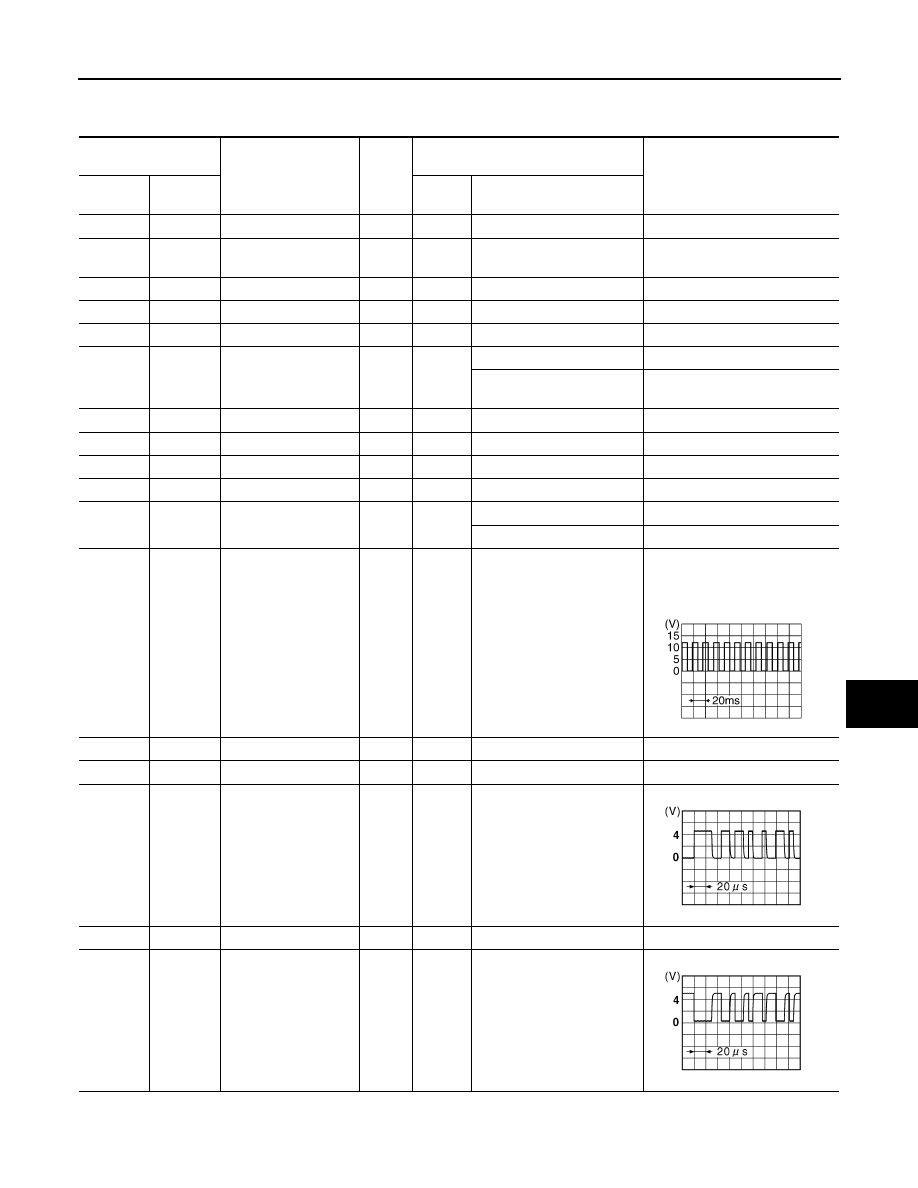
16 (G)
Ground
Vehicle speed signal
(8-pulse)
Input
ON
When vehicle speed is ap-
prox. 25 MPH (40 km/h)
NOTE:
Maximum voltage may be 5 V
due to specifications (connected
units).
25 (L)
—
CAN-H
—
—
—
—
26 (P)
—
CAN-L
—
—
—
—
28 (PU)
Ground
Communication
signal (+)
Input/
Output
ON
—
29
—
Shield
—
—
—
—
30 (LG)
Ground
Communication
signal (–)
Input/
Output
ON
—
PKIA1935E
SKIB7378E
SKIB7379E
AV-68
< SERVICE INFORMATION >
INTEGRATED DISPLAY SYSTEM
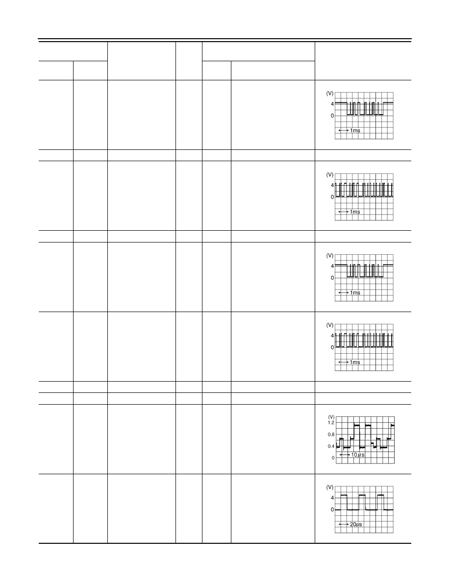
36 (PU)
Ground
Communication signal
(DCU-DSP)
Output
ON
—
37
—
Shield
—
—
—
—
38 (LG)
Ground
Communication signal
(DSP-DCU)
Input
ON
—
39
—
Shield
—
—
—
—
40 (LG)
Ground
Communication signal
(DCU-AUD)
Output
ON
Operate audio volume
switch
42 (PU)
Ground
Communication signal
(AUD-DCU)
Input
ON
Operate audio volume
switch
47
—
Shield
—
—
—
—
49
—
Shield
—
—
—
—
50 (G)
Ground
RGB signal (R: red)
Output
ON
Start Confirmation/Adjust-
ment mode, and then dis-
play color bar by selecting
“Display Color Spectrum
Bar” on Display Diagnosis
screen
51 (B)
Ground
RGB area (YS) signal
Output
ON
Set the selector lever in R
position, and then display
the rear view image
Terminal
(Wire color)
Item
Signal
input/
output
Condition
Reference value
+
–
Ignition
switch
Operation
SKIB3607E
SKIB3606E
SKIB3607E
SKIB3606E
SKIB7769E
SKIB3599E
INTEGRATED DISPLAY SYSTEM
AV-69
< SERVICE INFORMATION >
C
D
E
F
G
H
I
J
L
M
A
B
AV
N
O
P
Terminal and Reference Value for Display
INFOID:0000000001328719
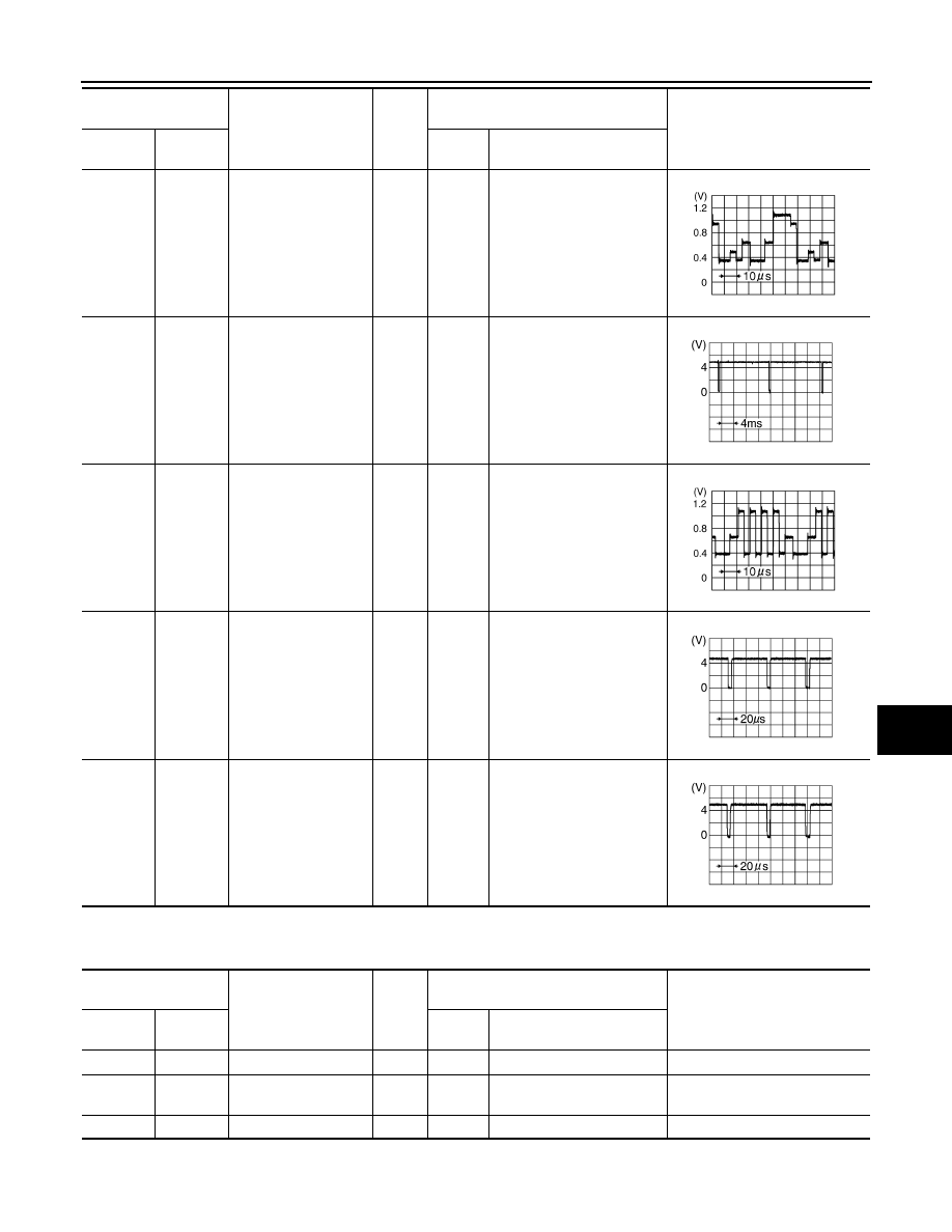
52 (Y)
Ground
RGB signal (G: green)
Output
ON
Start Confirmation/Adjust-
ment mode, and then dis-
play color bar by selecting
“Display Color Spectrum
Bar” on Display Diagnosis
screen
53 (W)
Ground
Vertical
synchronizing (VP)
signal
Input
ON
—
54 (L)
Ground
RGB signal (B: blue)
Output
ON
Start Confirmation/Adjust-
ment mode, and then dis-
play color bar by selecting
“Display Color Spectrum
Bar” on Display Diagnosis
screen
55 (R)
Ground
Horizontal
synchronizing (HP)
signal
Input
ON
—
56 (G)
Ground
RGB synchronizing
signal
Output
ON
When displaying RGB im-
age
Terminal
(Wire color)
Item
Signal
input/
output
Condition
Reference value
+
–
Ignition
switch
Operation
SKIB7770E
SKIB3598E
SKIB7771E
SKIB3601E
SKIB3603E
Terminal
(Wire color)
Item
Signal
input/
output
Condition
Reference value
+
–
Ignition
switch
Operation
1 (B)
Ground
Ground
—
ON
—
Approx. 0 V
2 (W/G)
Ground
Power supply (Invert-
er)
Input
ON
—
Approx. 9 V
3 (BR/W)
Ground
Power supply (Signal)
Input
ON
—
Approx. 9 V
Нет комментариевНе стесняйтесь поделиться с нами вашим ценным мнением.
Текст