Infiniti FX35 / FX45. Manual — part 154
AV-70
< SERVICE INFORMATION >
INTEGRATED DISPLAY SYSTEM
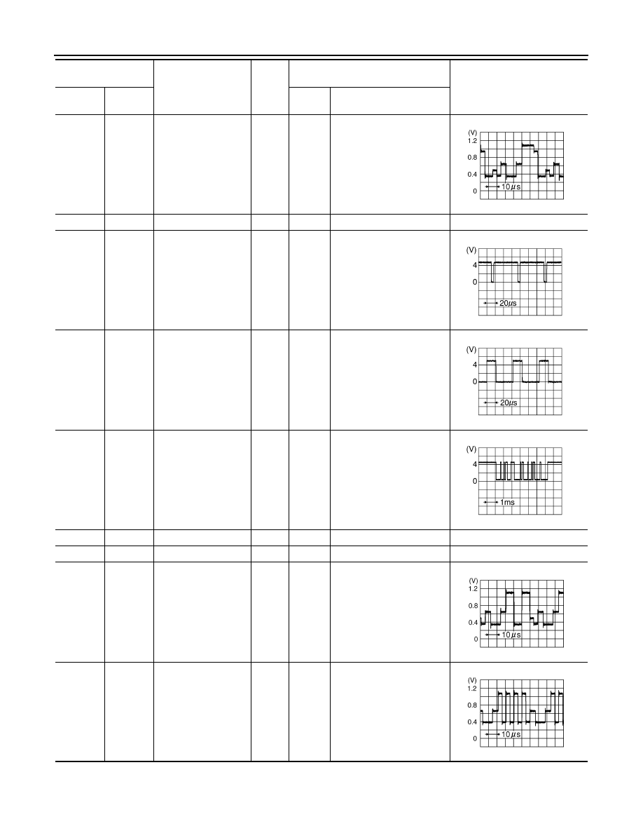
6 (Y)
Ground
RGB signal (G: green)
Input
ON
Start Confirmation/Adjust-
ment mode, and then dis-
play color bar by selecting
“Display Color Spectrum
Bar” on Display Diagnosis
screen
7
—
Shield
—
—
—
—
8 (R)
Ground
Horizontal
synchronizing (HP)
signal
Output
ON
—
9 (B)
Ground
RGB area (YS) signal
Input
ON
Set the selector lever in R
position, and then display
the rear view image
11 (PU)
Ground
Communication signal
(DCU-DSP)
Input
ON
—
13 (P)
Ground
Ground (Inverter)
—
ON
—
Approx. 0 V
14 (P/L)
Ground
Ground (Signal)
—
ON
—
Approx. 0 V
17 (G)
Ground
RGB signal (R: red)
Input
ON
Start Confirmation/Adjust-
ment mode, and then dis-
play color bar by selecting
“Display Color Spectrum
Bar” on Display Diagnosis
screen
18 (L)
Ground
RGB signal (B: blue)
Input
ON
Start Confirmation/Adjust-
ment mode, and then dis-
play color bar by selecting
“Display Color Spectrum
Bar” on Display Diagnosis
screen
Terminal
(Wire color)
Item
Signal
input/
output
Condition
Reference value
+
–
Ignition
switch
Operation
SKIB7770E
SKIB3601E
SKIB3599E
SKIB3607E
SKIB7769E
SKIB7771E
INTEGRATED DISPLAY SYSTEM
AV-71
< SERVICE INFORMATION >
C
D
E
F
G
H
I
J
L
M
A
B
AV
N
O
P
Terminal and Reference Value for A/C and AV Switch
INFOID:0000000001328720
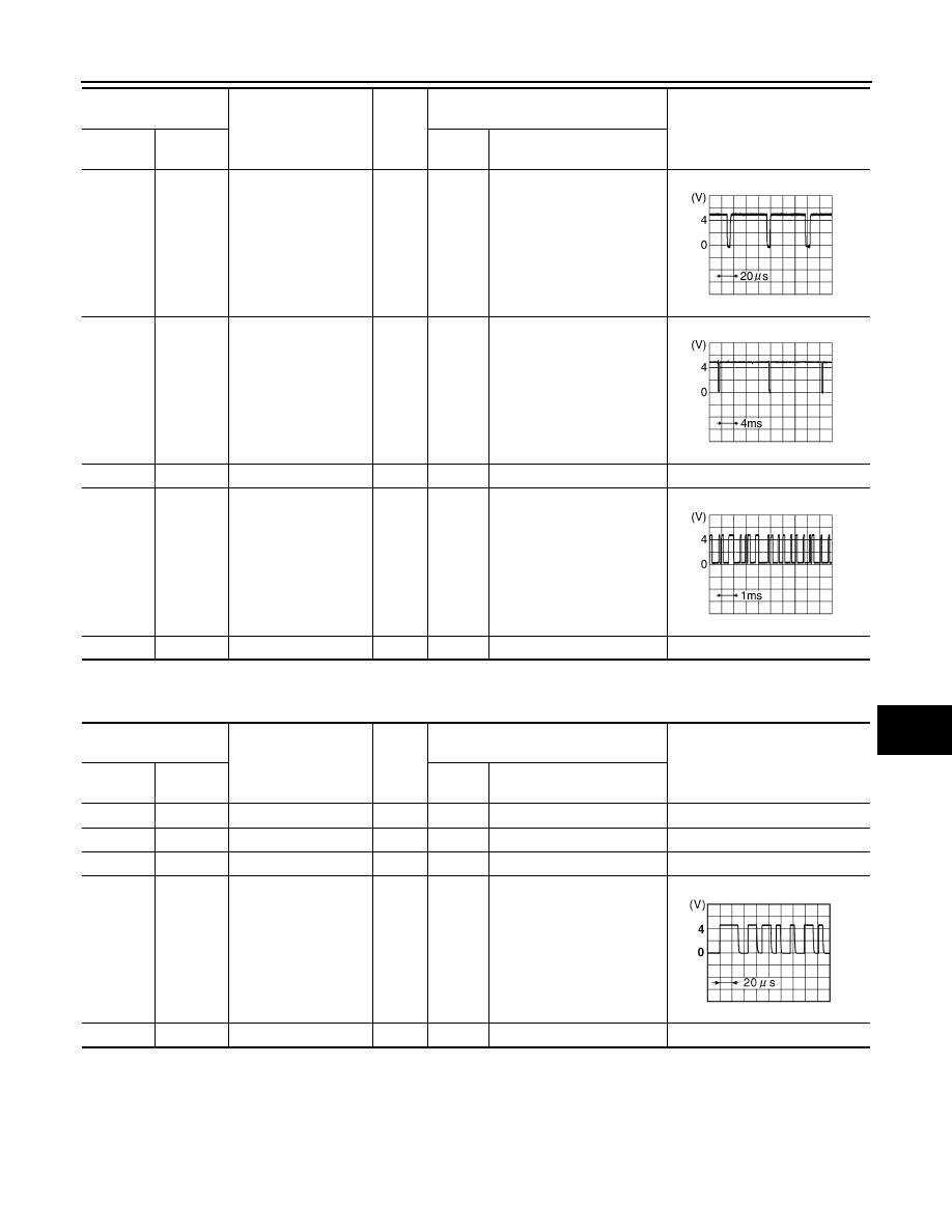
19 (G)
Ground
RGB synchronizing
signal
Input
ON
When displaying RGB im-
age
20 (W)
Ground
Vertical
synchronizing (VP)
signal
Output
ON
—
21
—
Shield
—
—
—
—
22 (LG)
Ground
Communication signal
(DSP-DCU)
Output
ON
—
23
—
Shield
—
—
—
—
Terminal
(Wire color)
Item
Signal
input/
output
Condition
Reference value
+
–
Ignition
switch
Operation
SKIB3603E
SKIB3598E
SKIB3606E
Terminal
(Wire color)
Item
Signal
input/
output
Condition
Reference value
+
–
Ignition
switch
Operation
1 (W/L)
Ground
Battery power supply
Input
OFF
—
Battery voltage
2 (LG)
Ground
ACC power supply
Input
ACC
—
Battery voltage
5 (B)
Ground
Ground
—
ON
—
Approx. 0 V
6 (PU)
Ground
Communication
signal (+)
Input/
Output
ON
—
7
—
Shield
—
—
—
—
SKIB7378E
AV-72
< SERVICE INFORMATION >
INTEGRATED DISPLAY SYSTEM
• *1: With telephone system
• *2: Without telephone system
Special Note for Trouble Diagnosis
INFOID:0000000001328721
Prior to performing trouble diagnosis, make sure there are no corresponding description in the “Example of
Symptoms Possible No Malfunction”. Refer to
AV-86, "Example of Symptom Possible No Malfunction"
On Board Self-Diagnosis Function
INFOID:0000000001328722
DESCRIPTION
• Trouble diagnosis function of navigation system has a Self Diagnosis mode by automatic operation and a
Confirmation/Adjustment mode by manual operation.
• Self Diagnosis mode checks for connections between the units constituting this system, analyzes each indi-
vidual unit at the same time, and displays the results on the display.
• Confirmation/Adjustment mode displays trouble diagnosis that require an operation and a judgment by a
human (auto-decision cannot be performed by the system), confirmation of preset value, and an error his-
tory.
DIAGNOSIS ITEM
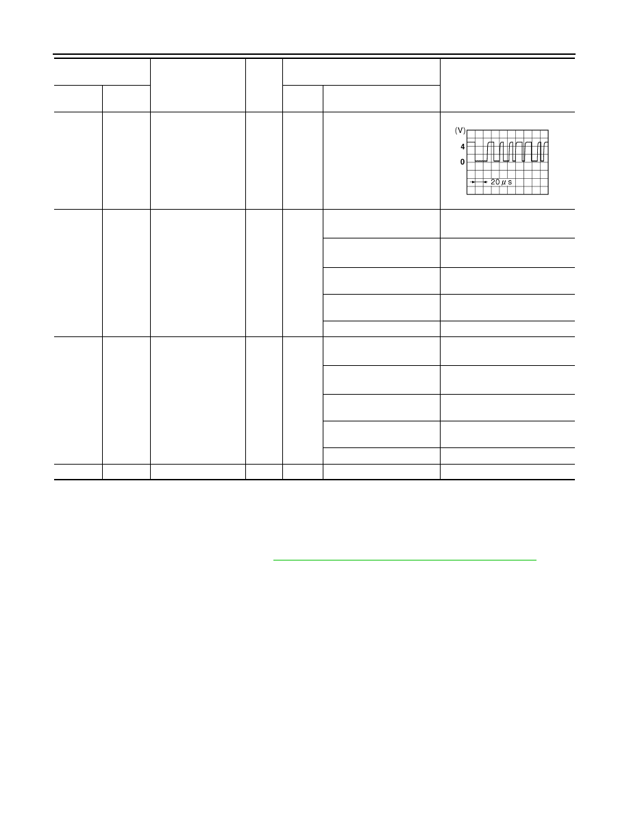
8 (LG)
Ground
Communication
signal (–)
Input/
Output
ON
—
12 (R/W)
Ground
Steering SW A
Input
ON
Press and hold PTT
*1
switch
Approx. 0 V
Press and hold MODE
*2
switch
Approx. 0 V
Press and hold SEEK UP
switch
Approx. 1.7 V
Press and hold VOL UP
switch
Approx. 3.3 V
Except for above
Approx. 5 V
13 (G/W)
Ground
Steering SW B
Input
ON
Press and hold MODE
*1
switch
Approx. 0 V
Press and hold POWER
*2
switch
Approx. 0 V
Press and hold SEEK
DOWN switch
Approx. 1.7 V
Press and hold VOL DOWN
switch
Approx. 3.3 V
Except for above
Approx. 5 V
14 (B/Y)
Ground
Steering SW ground
—
ON
—
Approx. 0 V
Terminal
(Wire color)
Item
Signal
input/
output
Condition
Reference value
+
–
Ignition
switch
Operation
SKIB7379E
INTEGRATED DISPLAY SYSTEM
AV-73
< SERVICE INFORMATION >
C
D
E
F
G
H
I
J
L
M
A
B
AV
N
O
P
Self-Diagnosis Mode (DCU)
INFOID:0000000001328723
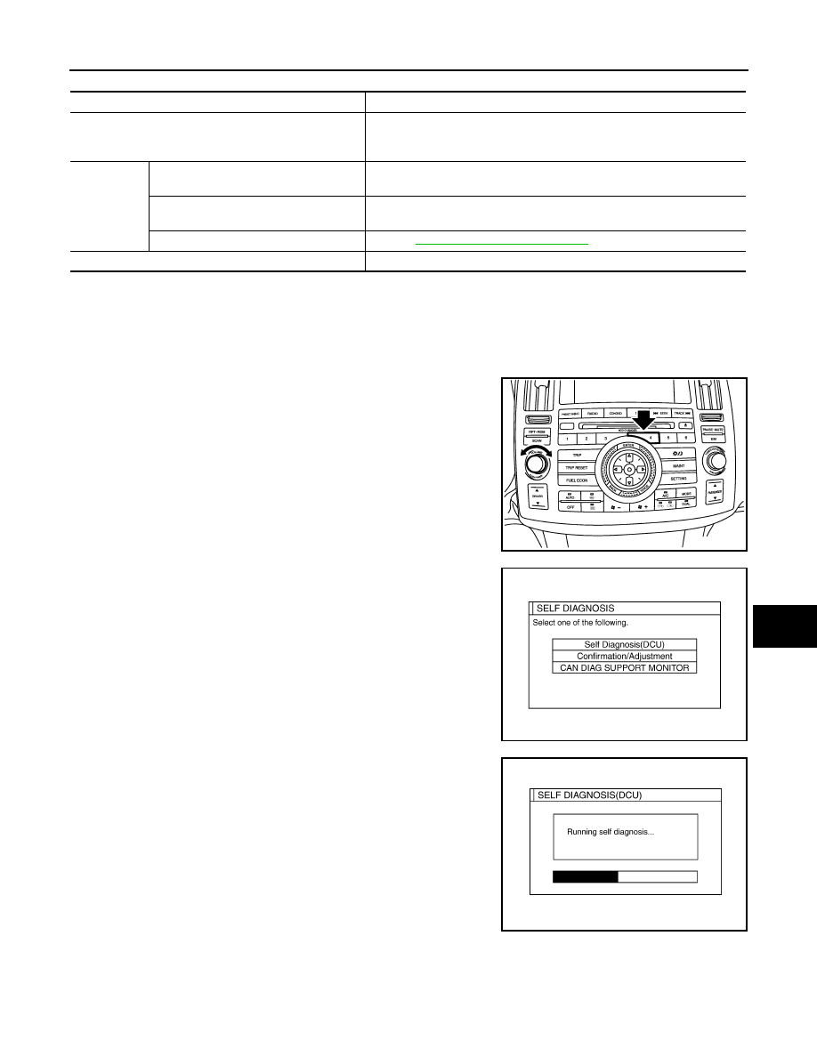
OPERATION PROCEDURE
1.
Start the engine.
2.
Turn the audio system OFF.
3.
While pressing the “4” button, turn the volume control dial clock-
wise or counterclockwise for 30 clicks or more. (When the self-
diagnosis mode is started, a short beep will be heard.)
• Shifting from current screen to previous screen is performed
by pressing “BACK” button.
4.
The initial trouble diagnosis screen will be shown, and items
“Self Diagnosis (DCU)”, “Confirmation/Adjustment” and “CAN
DIAG SUPPORT MONITOR” will become selective.
5.
Perform self-diagnosis by selecting the “Self Diagnosis (DCU)”.
• Self-diagnosis screen is displayed, and then self-diagnosis
starts.
• The bar graph visible below self-diagnosis screen displays
progress of the diagnosis.
Mode
Description
Self Diagnosis (DCU)
• Display control unit diagnosis
• Analyzes connection between the display control unit and each unit, and
operation of each unit.
Confirmation/
Adjustment
Display Diagnosis
Color tone and shading of the display control unit-generated image can be
checked by the display of a color bar and a gray scale.
Vehicle Signals
Diagnosis of signals that are input to display control unit can be performed
for Vehicle Speed, IGN, Reverse and Light.
Auto Climate Control
ATC-43, "Self-Diagnosis Function"
CAN DIAG SUPPOPT MONITOR
The transmitting/receiving of CAN communication can be monitored.
SKIB8743E
SKIB7871E
SKIA4208E
Нет комментариевНе стесняйтесь поделиться с нами вашим ценным мнением.
Текст