Infiniti FX35 / FX45. Manual — part 147
AV-42
< SERVICE INFORMATION >
AUDIO
Installation is the reverse order of removal.
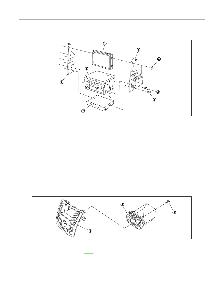
Disassembly and Assembly of Audio Unit
INFOID:0000000001328692
DISASSEMBLY
Remove audio unit screws (8) and display screws (4) and unified meter and A/C amp. screws (2) with power
tool and remove brackets.
ASSEMBLY
Assembly is the reverse order of disassembly.
NOTE:
Use appropriate screws for each, as screws for audio unit and display unit are different from that for unified
meter and A/C amp.
Removal and Installation for A/C and AV Switch
INFOID:0000000001328693
REMOVAL
1.
Remove cluster lid C (1). Refer to
2.
Remove screws (3) and remove A/C and AV switch (2) from cluster lid C (1).
INSTALLATION
Installation is the reverse order of removal.
1.
Display
2.
Bracket (LH)
3.
Audio unit
4.
Screw (For metal)
5.
Screw (For plastic)
6.
Bracket (RH)
7.
Unified meter and A/C amp.
SKIB8678E
1.
Cluster lid C
2.
A/C and AV switch
3.
Screws
PKID0425E
AUDIO
AV-43
< SERVICE INFORMATION >
C
D
E
F
G
H
I
J
L
M
A
B
AV
N
O
P
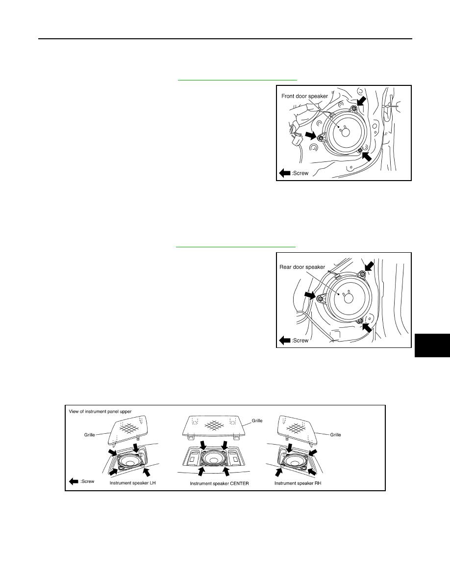
Removal and Installation for Front Door Speaker
INFOID:0000000001328694
REMOVAL
1.
Remove front door finisher. Refer to
EI-36, "Component Parts Location"
.
2.
Remove screws (3) and remove front door speaker.
INSTALLATION
Installation is the reverse order of removal.
Removal and Installation for Rear Door Speaker
INFOID:0000000001328695
REMOVAL
1.
Remove rear door finisher. Refer to
EI-36, "Component Parts Location"
2.
Remove screws (3) and remove rear door speaker.
INSTALLATION
Installation is the reverse order of removal.
Removal and Installation for Instrument Speaker
INFOID:0000000001328696
REMOVAL
1.
Remove grille from instrument panel.
2.
Remove screws (4) and disconnect connector.
3.
Remove instrument speaker.
INSTALLATION
Installation is the reverse order of removal.
SKIA5803E
SKIA5804E
SKIA5805E
AV-44
< SERVICE INFORMATION >
AUDIO
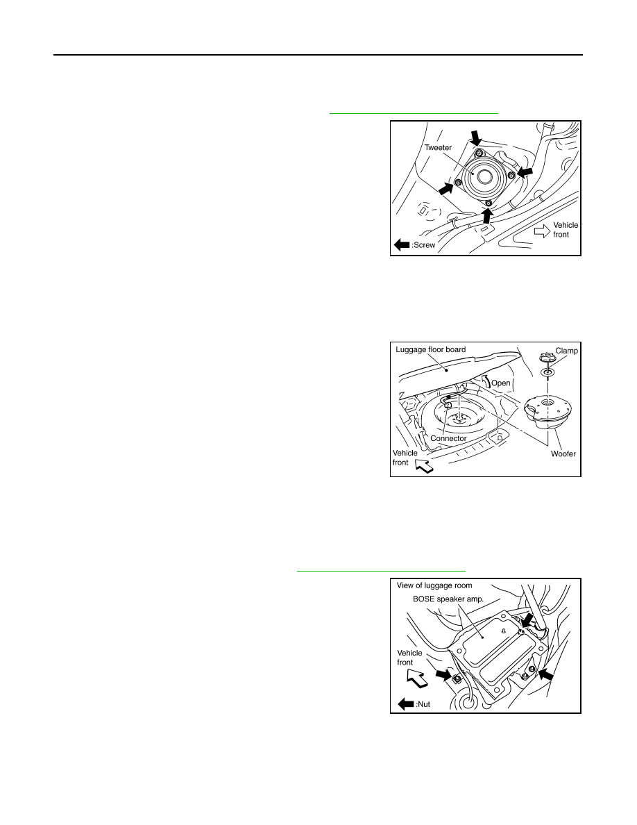
Removal and Installation for Tweeter
INFOID:0000000001328697
REMOVAL
1.
Remove rear pillar upper garnish assembly. Refer to
EI-45, "Component Parts Location"
.
2.
Remove screws (4), and disconnect connector.
3.
Remove tweeter.
INSTALLATION
Installation is the reverse order of removal.
Removal and Installation for Woofer (BOSE System)
INFOID:0000000001328698
REMOVAL
1.
Open luggage floor board.
2.
Remove speaker clamp and harness clip.
3.
Disconnect connector.
4.
Remove woofer.
CAUTION:
Connectors must be placed in the left side, when installed.
INSTALLATION
Installation is the reverse order of removal.
Removal and Installation for BOSE Speaker Amp
INFOID:0000000001328699
REMOVAL
1.
Remove luggage side box assembly. Refer to
EI-45, "Component Parts Location"
.
2.
Remove nuts (3) with power tool, and remove BOSE speaker
amp. from luggage room floor.
SKIA5806E
SKIA5807E
SKIB8776E
AUDIO
AV-45
< SERVICE INFORMATION >
C
D
E
F
G
H
I
J
L
M
A
B
AV
N
O
P
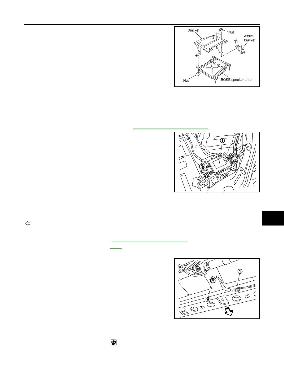
3.
Remove nuts (2) with power tool, and remove assist bracket.
4.
Remove nuts (4) with power tool, and remove bracket.
INSTALLATION
Installation is the reverse order of removal.
Removal and Installation of Satellite Radio Tuner
INFOID:0000000001328700
REMOVAL
1.
Remove luggage side box assembly. Refer to
EI-45, "Component Parts Location"
.
2.
Remove nuts (A) and remove satellite radio tuner (1) from lug-
gage room floor.
INSTALLATION
Installation is the reverse order of removal.
Removal and Installation of Satellite Radio Antenna
INFOID:0000000001328701
: Vehicle front
REMOVAL
1.
Remove luggage floor trim. Refer to
EI-45, "Component Parts Location"
.
2.
Remove assist grip (rear). Refer to
3.
Pull down headlining and obtain space for work between vehicle and headlining.
4.
Remove nut (A), and then disconnect connector (1).
5.
Remove satellite radio antenna.
INSTALLATION
Installation is the reverse order of removal.
SKIA5809E
SKIB8650E
SKIB8668E
Roof antenna mounting nut
: 4.5 N·m (0.46 kg-m, 40 in-lb)
Нет комментариевНе стесняйтесь поделиться с нами вашим ценным мнением.
Текст