Infiniti FX35 / FX45. Manual — part 146
AV-38
< SERVICE INFORMATION >
AUDIO
NO
>> • GO TO 2. (Without telephone system)
• GO TO 3. (With telephone system)
2.
CHECK HARNESS
1.
Turn ignition switch OFF.
2.
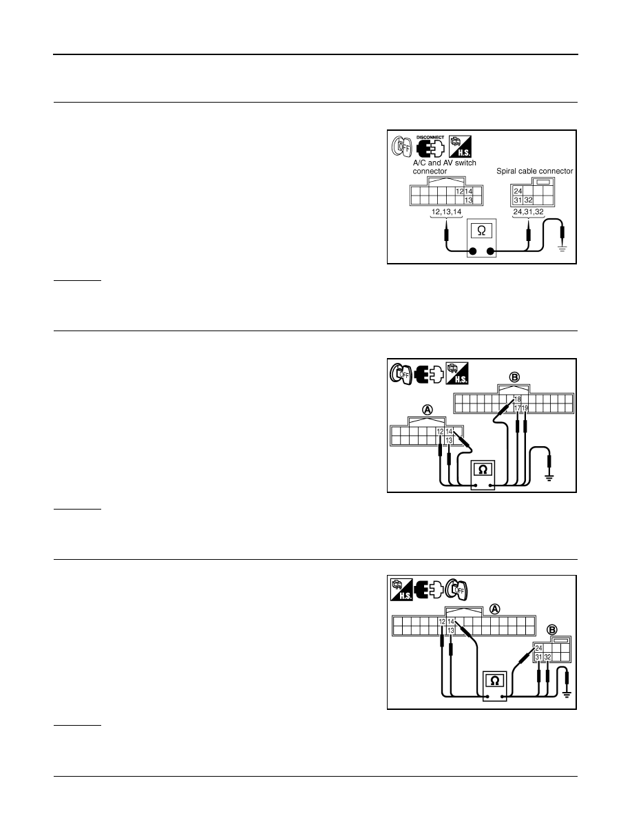
Disconnect A/C and AV switch and spiral cable connectors.
3.
Check continuity between A/C and AV switch harness connector
M64 terminals 12, 13, 14 and spiral cable harness connector
M15 terminals 24, 32, 31.
4.
Check continuity between A/C and AV switch and ground.
OK or NG
OK
>> GO TO 5.
NG
>> Repair harness or connector.
3.
CHECK HARNESS
1.
Turn ignition switch OFF.
2.
Disconnect A/C and AV switch and TEL adapter unit connectors.
3.
Check continuity between A/C and AV switch harness connector
(A) M64 terminals 12, 13, 14 and teladapter unit harness con-
nector (B) M102 terminals 17, 18, 19.
4.
Check continuity between A/C and AV switch and ground.
OK or NG
OK
>> GO TO 4.
NG
>> Repair harness or connector.
4.
CHECK HARNESS
1.
Disconnect spiral cable connector.
2.
Check continuity between TEL adapter unit harness connector
(A) M102 terminals 12, 13, 14 and spiral cable harness connec-
tor (B) M15 terminals 24, 32, 31.
3.
Check continuity between TEL adapter unit and ground.
OK or NG
OK
>> GO TO 5.
NG
>> Repair harness or connector.
5.
CHECK SPIRAL CABLE
1.
Disconnect spiral cable connector (Audio steering wheel switch harness side).
12 – 24
: Continuity should exist.
13 – 32
: Continuity should exist.
14 – 31
: Continuity should exist.
12, 13, 14 – ground
: Continuity should not exist.
SKIA5955E
12 – 17
: Continuity should exist.
13 – 18
: Continuity should exist.
14 – 19
: Continuity should exist.
12, 13, 14 – ground
: Continuity should not exist.
PKIC9369E
12 – 24
: Continuity should exist.
13 – 32
: Continuity should exist.
14 – 31
: Continuity should exist.
12, 13, 14 – ground
: Continuity should not exist.
SKIB8681E
AUDIO
AV-39
< SERVICE INFORMATION >
C
D
E
F
G
H
I
J
L
M
A
B
AV
N
O
P
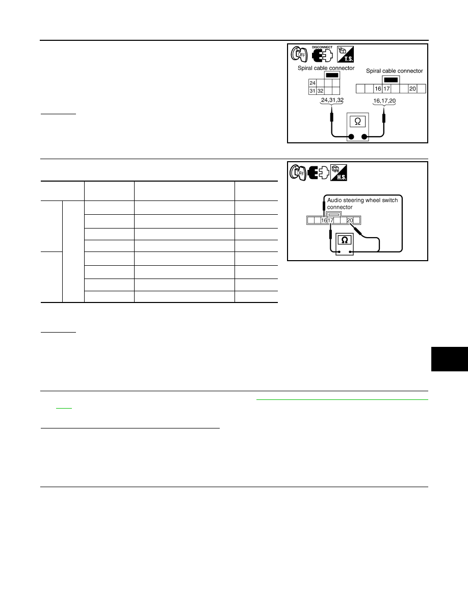
2.
Check continuity between spiral cable connector M15 terminals
24, 31, 32 and spiral cable connector M203 terminals 20, 17, 16.
OK or NG
OK
>> GO TO 6.
NG
>> Replace spiral cable.
6.
CHECK AUDIO STEERING WHEEL SWITCH RESISTANCE
Check resistance audio steering wheel switch terminals.
• *1: Without telephone system
• *2: With telephone system
OK or NG
OK
>> INSPECTION END
NG
>> Replace audio steering wheel switch.
A/C and AV Switch Inspection
INFOID:0000000001328687
1.
A/C AND AV SWITCH SELF-DIAGNOSIS FUNCTION
1.
Start A/C and AV switch self-diagnosis function. Refer to
AV-34, "A/C and AV Switch Self-Diagnosis Func-
2.
Operate A/C and AV switch.
Does the A/C and AV switch is operated normally?
YES
>> INSPECTION END (System is OK)
NO
>> Replace A/C and AV switch.
BOSE Speaker Amp. Inspection
INFOID:0000000001328688
1.
CHECK HARNESS
1.
Turn ignition switch OFF.
2.
Disconnect audio unit and BOSE speaker amp. connectors.
24 – 20
: Continuity should exist.
31 – 17
: Continuity should exist.
32 – 16
: Continuity should exist.
SKIA5874E
Terminal
Signal name
Condition
Resistance
(
Ω
)
16
17
Power
*1
Depress power switch.
Approx. 0
Mode
*2
Depress mode switch.
Approx. 0
Seek down
Depress (station) down switch.
Approx. 165
Volume (down)
Depress volume down switch.
Approx. 652
20
Mode
*1
Depress mode switch.
Approx. 0
PTT
*2
Depress PTT switch.
Approx. 0
Seek up
Depress (station) up switch.
Approx. 165
Volume (up)
Depress volume up switch.
Approx. 652
SKIA5010E

AV-40
< SERVICE INFORMATION >
AUDIO
3.
Check continuity between audio unit harness connector M59 ter-
minal 12 and BOSE speaker amp. harness connector B213 ter-
minal 31.
4.
Check continuity between audio unit harness connector M59 ter-
minal 12 and ground.
OK or NG
OK
>> GO TO 2.
NG
>> Repair harness or connector.
2.
CHECK AMP. ON SIGNAL
1.
Connect audio unit connector.
2.
Turn ignition switch ACC.
3.
Check voltage between audio unit harness connector M59 ter-
minal 12 and ground.
OK or NG
OK
>> INSPECTION END (System is OK.)
NG
>> Replace audio unit.
Vehicle Speed Signal Inspection
INFOID:0000000001328689
1.
CHECK VEHICLE SPEED OPERATION
Start engine and drive vehicle.
Dose speedometer is operated normally?
YES
>> GO TO 2.
NO
>> Check combination meter trouble diagnosis. Refer to
.
2.
CHECK HARNESS
1.
Turn ignition switch OFF.
2.
Disconnect audio unit and unified meter and A/C amp. connectors.
3.
Check continuity between audio unit harness connector M60 ter-
minal 22 and unified meter and A/C amp. harness connector
M56 terminal 34.
4.
Check continuity between audio unit harness connector M60 ter-
minal 22 and ground.
OK or NG
OK
>> GO TO 3.
NG
>> Repair harness or connector.
3.
CHECK VEHICLE SPEED SIGNAL
1.
Connect audio unit and unified meter and A/C amp. connectors.
2.
Start engine and drive vehicle at more than 40 km/h (25 MPH).
12 – 31
: Continuity should exist.
12 – Ground
: Continuity should not exist.
SKIA6816E
12 – Ground
: Approx. 12 V
SKIA6818E
22 – 34
: Continuity should exist.
22 – Ground
: Continuity should not exist.
SKIA6807E
AUDIO
AV-41
< SERVICE INFORMATION >
C
D
E
F
G
H
I
J
L
M
A
B
AV
N
O
P
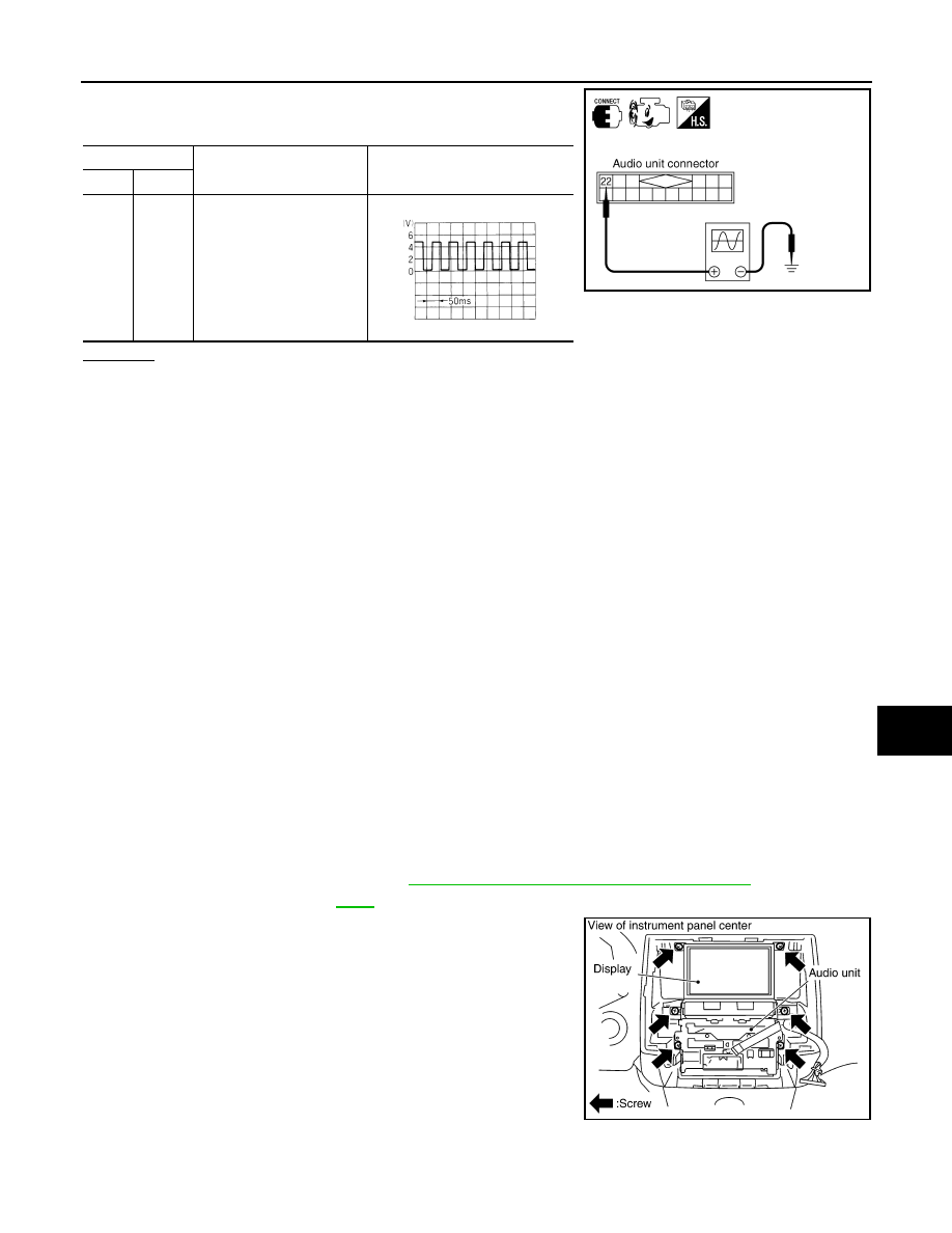
3.
Check the signal between audio unit harness connector M60
terminal 22 and ground with CONSULT-III or oscilloscope.
OK or NG
OK
>> INSPECTION END (System is OK.)
NG
>> Replace unified meter and A/C amp.
Locking CD Auto-Changer Mechanism
INFOID:0000000001328690
CAUTION:
• Prior to removing a malfunctioning CD auto-changer unit that will be shipped for repair, the changer
mechanism MUST BE LOCKED to prevent the mechanism from being damaged during shipping.
• If a CD is jammed or unable to be removed from the unit, do NOT lock the changer mechanism. If the
unit is to be shipped for repair, carefully package the unit to prevent vibration and shock.
DAMPER LOCK PROCEDURE
1.
Eject and remove any CDs from the audio unit.
2.
Turn ignition switch OFF. Wait until audio unit display is off and mechanism stops moving (mechanism
sound stops).
3.
Press any one of the disc selection buttons once. When a display shows on the audio unit, press the
same disc selection button again within 5 seconds.
• The changer mechanism will lock itself within 10 seconds.
4.
After mechanism stops moving (mechanism sound stops), open the driver and passenger window, and
then disconnect negative battery cable.
NOTE:
After installing a new or remanufactured audio unit, switching the audio unit ON will automatically unlock the
mechanism. A special unlocking procedure is not required.
Removal and Installation of Audio Unit
INFOID:0000000001328691
REMOVAL
1.
Perform damper lock operation. Refer to
AV-41, "Locking CD Auto-Changer Mechanism"
2.
Remove cluster lid C. Refer to
.
3.
Remove screws (6) with power tool, and remove audio unit with
display and unified meter and A/C amp. from instrument panel.
4.
Remove screws and remove audio unit.
INSTALLATION
Terminal
Condition
Reference
signal
(+)
(–)
22
Ground
When vehicle speed is ap-
prox. 40 km/h (25 MPH)
SKIA6809E
ELF1080D
SKIA5800E
Нет комментариевНе стесняйтесь поделиться с нами вашим ценным мнением.
Текст