Infiniti FX35 / FX45. Manual — part 477

TROUBLE DIAGNOSIS
EC-669
< SERVICE INFORMATION >
[VK45DE]
C
D
E
F
G
H
I
J
K
L
M
A
EC
N
P
O
Are they within the SP value?
Yes
>> GO TO 9.
No
>> GO TO 8.
8.
DETECT MALFUNCTIONING PART BY TROUBLE DIAGNOSIS - SPECIFICATION VALUE
Detect malfunctioning part according to
Is malfunctioning part detected?
Yes
>> GO TO 11.
No
>> GO TO 9.
9.
DETECT MALFUNCTIONING SYSTEM BY SYMPTOM MATRIX CHART
Detect malfunctioning system according to
EC-673, "Symptom Matrix Chart"
based on the confirmed symptom
in step 4, and determine the trouble diagnosis order based on possible causes and symptom.
>> GO TO 10.
10.
DETECT MALFUNCTIONING PART BY DIAGNOSTIC PROCEDURE
Inspect according to Diagnostic Procedure of the system.
NOTE:
The Diagnostic Procedure in EC section described based on open circuit inspection. A short circuit inspection
is also required for the circuit check in the Diagnostic Procedure. For details, refer to Circuit Inspection in
25, "How to Perform Efficient Diagnosis for an Electrical Incident"
Is malfunctioning part detected?
Yes
>> GO TO 11.
No
>> Monitor input data from related sensors or check voltage of related ECM terminals using CON-
SULT-III. Refer to
EC-705, "CONSULT-III Reference Value in Data Monitor Mode"
11.
REPAIR OR REPLACE THE MALFUNCTIONING PART
1.
Repair or replace the malfunctioning part.
2.
Reconnect parts or connectors disconnected during Diagnostic Procedure again after repair and replace-
ment.
3.
Check DTC. If DTC is displayed, erase it, refer to
EC-633, "Emission-related Diagnostic Information"
.
>> GO TO 12.
12.
FINAL CHECK
When DTC was detected in step 2, perform DTC Confirmation Procedure or Overall Function Check again,
and then make sure that the malfunction have been repaired securely.
When symptom was described from the customer, refer to confirmed symptom in step 3 or 4, and make sure
that the symptom is not detected.
OK or NG
NG (DTC*
1
is detected)>>GO TO 10.
NG (Symptom remains)>>GO TO 6.
OK
>> 1.
Before returning the vehicle to the customer, make sure to erase unnecessary DTC*
1
in ECM
and TCM (Transmission Control Module). (Refer to
EC-633, "Emission-related Diagnostic
and
AT-38, "OBD-II Diagnostic Trouble Code (DTC)"
.)
2.
If the completion of SRT is needed, drive vehicle under the specific driving pattern. Refer to
EC-633, "Emission-related Diagnostic Information"
3.
INSPECTION END
*1: Include 1st trip DTC.
*2: Include 1st trip freeze frame data.
DIAGNOSTIC WORKSHEET
Description
EC-670
< SERVICE INFORMATION >
[VK45DE]
TROUBLE DIAGNOSIS
There are many operating conditions that lead to the malfunction of
engine components. A good grasp of such conditions can make trou-
bleshooting faster and more accurate.
In general, each customer feels differently about a incident. It is
important to fully understand the symptoms or conditions for a cus-
tomer complaint.
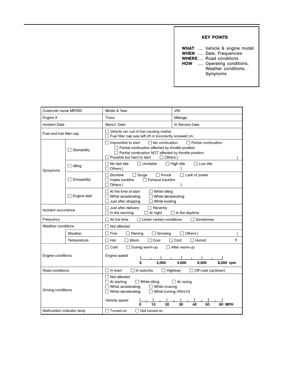
Utilize a diagnostic worksheet like the one on the next page in order
to organize all the information for troubleshooting.
Some conditions may cause the MIL to come on steady or blink and
DTC to be detected. Examples:
• Vehicle ran out of fuel, which caused the engine to misfire.
• Fuel filler cap was left off or incorrectly screwed on, allowing fuel to
evaporate into the atmosphere.
Worksheet Sample
DTC Inspection Priority Chart
INFOID:0000000001326524
If some DTCs are displayed at the same time, perform inspections one by one based on the following priority
chart.
SEF907L
MTBL0017

TROUBLE DIAGNOSIS
EC-671
< SERVICE INFORMATION >
[VK45DE]
C
D
E
F
G
H
I
J
K
L
M
A
EC
N
P
O
Fail-Safe Chart
INFOID:0000000001326525
When the DTC listed below is detected, the ECM enters fail-safe mode and the MIL lights up.
Priority
Detected items (DTC)
1
• U1000 U1001 CAN communication line
• U1010 CAN communication
• P0101 P0102 P0103 Mass air flow sensor
• P0112 P0113 P0127 Intake air temperature sensor
• P0117 P0118 P0125 Engine coolant temperature sensor
• P0122 P0123 P0222 P0223 P1225 P1226 P2135 Throttle position sensor
• P0128 Thermostat function
• P0181 P0182 P0183 Fuel tank temperature sensor
• P0327 P0328 P0332 P0333 Knock sensor
• P0335 Crankshaft position sensor (POS)
• P0340 Camshaft position sensor (PHASE)
• P0460 P0461 P0462 P0463 Fuel level sensor
• P0500 Vehicle speed sensor
• P0605 ECM
• P0643 Sensor power supply
• P0700 TCM
• P0705 Park/neutral position (PNP) switch
• P0850 Park/neutral position (PNP) switch
• P1610 - P1615 NATS
• P2122 P2123 P2127 P2128 P2138 Accelerator pedal position sensor
2
• P0031 P0032 P0051 P0052 Air fuel ratio (A/F) sensor 1 heater
• P0037 P0038 P0057 P0058 Heated oxygen sensor 2 heater
• P0075 P0081 Intake valve timing control solenoid valve
• P0130 P0131 P0132 P0133 P0150 P0151 P0152 P0153 P2A00 P2A03 Air fuel ratio (A/F) sensor 1
• P0137 P0138 P0139 P0157 P0158 P0159 Heated oxygen sensor 2
• P0441 EVAP control system purge flow monitoring
• P0443 P0444 P0445 EVAP canister purge volume control solenoid valve
• P0447 P0448 EVAP canister vent control valve
• P0451 P0452 P0453 EVAP control system pressure sensor
• P0550 Power steering pressure sensor
• P0603 ECM power supply
• P0710 P0717 P0720 P0731 P0732 P0733 P0734 P0735 P0740 P0744 P0745 P1730 P1752 P1757 P1762 P1767
P1772 P1774 A/T related sensors, solenoid valves and switches
• P1140 P1145 Intake valve timing control position sensor
• P1217 Engine over temperature (OVERHEAT)
• P1805 Brake switch
• P2100 P2103 Throttle control motor relay
• P2101 Electric throttle control function
• P2118 Throttle control motor
3
• P0011 P0021 Intake valve timing control
• P0171 P0172 P0174 P0175 Fuel injection system function
• P0300 - P0308 Misfire
• P0420 P0430 Three way catalyst function
• P0442 P0456 EVAP control system (SMALL LEAK, VERY SMALL LEAK)
• P0455 EVAP control system (GROSS LEAK)
• P0506 P0507 Idle speed control system
• P1148 P1168 Closed loop control
• P1211 TCS control unit
• P1212 TCS communication line
• P1421 Cold start control
• P1564 ICC steering switch / ASCD steering switch
• P1568 ICC command value
• P1572 ICC brake switch / ASCD brake switch
• P1574 ICC vehicle speed sensor / ASCD vehicle speed sensor
• P1715 Turbine revolution sensor
• P1800 VIAS control solenoid valve
• P2119 Electric throttle control actuator

EC-672
< SERVICE INFORMATION >
[VK45DE]
TROUBLE DIAGNOSIS
• When there is an open circuit on MIL circuit, the ECM cannot warn the driver by lighting up MIL when there
is malfunction on engine control system.
Therefore, when electrical controlled throttle and part of ECM related diagnoses are continuously detected
as NG for 5 trips, ECM warns the driver that engine control system malfunctions and MIL circuit is open by
means of operating fail-safe function.
The fail-safe function also operates when above diagnoses except MIL circuit are detected and demands the
driver to repair the malfunction.
DTC No.
Detected items
Engine operating condition in fail-safe mode
P0102
P0103
Mass air flow sensor circuit
Engine speed will not rise more than 2,400 rpm due to the fuel cut.
P0117
P0118
Engine coolant tempera-
ture sensor circuit
Engine coolant temperature will be determined by ECM based on the following conditions.
CONSULT-III displays the engine coolant temperature decided by ECM.
Condition
Engine coolant temperature decided
(CONSULT-III display)
Just as ignition switch is turned ON
or START
40
°
C (104
°
F)
Approx. 4 minutes or more after
engine starting.
80
°
C (176
°
F)
Except as shown above
40 - 80
°
C (104 - 176
°
F)
(Depends on the time)
When the fail-safe system for engine coolant temperature sensor is activated, the cooling
fan operates while engine is running.
P0122
P0123
P0222
P0223
P2135
Throttle position sensor
The ECM controls the electric throttle control actuator in regulating the throttle opening in
order for the idle position to be within +10 degrees.
The ECM regulates the opening speed of the throttle valve to be slower than the normal
condition.
So, the acceleration will be poor.
P0643
Sensor power supply
ECM stops the electric throttle control actuator control, throttle valve is maintained at a
fixed opening (approx. 5 degrees) by the return spring.
P2100
P2103
Throttle control motor relay
ECM stops the electric throttle control actuator control, throttle valve is maintained at a
fixed opening (approx. 5 degrees) by the return spring.
P2101
Electric throttle control
function
ECM stops the electric throttle control actuator control, throttle valve is maintained at a
fixed opening (approx. 5 degrees) by the return spring.
P2118
Throttle control motor
ECM stops the electric throttle control actuator control, throttle valve is maintained at a
fixed opening (approx. 5 degrees) by the return spring.
P2119
Electric throttle control ac-
tuator
(When electric throttle control actuator does not function properly due to the return spring
malfunction:)
ECM controls the electric throttle actuator by regulating the throttle opening around the
idle position. The engine speed will not rise more than 2,000 rpm.
(When throttle valve opening angle in fail-safe mode is not in specified range:)
ECM controls the electric throttle control actuator by regulating the throttle opening to 20
degrees or less.
(When ECM detects the throttle valve is stuck open:)
While the vehicle is driving, it slows down gradually by fuel cut. After the vehicle stops, the
engine stalls.
The engine can restart in N or P position, and engine speed will not exceed 1,000 rpm or
more.
P2122
P2123
P2127
P2128
P2138
Accelerator pedal position
sensor
The ECM controls the electric throttle control actuator in regulating the throttle opening in
order for the idle position to be within +10 degrees.
The ECM regulates the opening speed of the throttle valve to be slower than the normal
condition.
So, the acceleration will be poor.
Engine operating condition in fail-safe mode
Engine speed will not rise more than 2,500 rpm due to the fuel cut
Нет комментариевНе стесняйтесь поделиться с нами вашим ценным мнением.
Текст