Infiniti FX35 / FX45. Manual — part 517
DTC P0133, P0153 A/F SENSOR 1
EC-829
< SERVICE INFORMATION >
[VK45DE]
C
D
E
F
G
H
I
J
K
L
M
A
EC
N
P
O
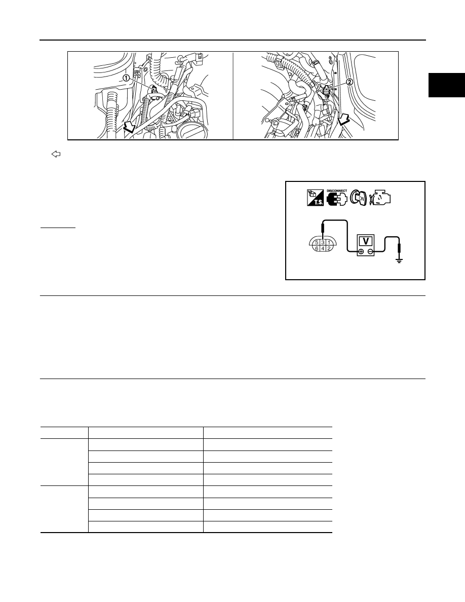
2.
Turn ignition switch ON.
3.
Check voltage between A/F sensor 1 terminal 3 and ground with
CONSULT-III or tester.
OK or NG
OK
>> GO TO 8.
NG
>> GO TO 7.
7.
DETECT MALFUNCTIONING PART
Check the following.
• Harness connectors E19, F49
• IPDM E/R connector E7
• 10A fuse
• Harness for open or short between A/F sensor 1 and fuse
>> Repair or replace harness or connectors.
8.
CHECK A/F SENSOR 1 INPUT SIGNAL CIRCUIT FOR OPEN AND SHORT
1.
Turn ignition switch OFF.
2.
Disconnect ECM harness connector.
3.
Check harness continuity between A/F sensor 1 terminal and ECM terminal as follows.
Refer to Wiring Diagram.
4.
Check harness continuity between the following terminals and ground.
Refer to Wiring Diagram.
: Vehicle front
1.
A/F sensor 1 (Bank 2) harness con-
nector
2.
A/F sensor 1 (Bank 1) harness con-
nector
Voltage: Battery voltage
PBIB3246E
PBIB1683E
A/F sensor 1 terminal
ECM terminal
Bank 1
1
16
2
75
5
35
6
56
Bank 2
1
76
2
77
5
57
6
58
Continuity should exist.

EC-830
< SERVICE INFORMATION >
[VK45DE]
DTC P0133, P0153 A/F SENSOR 1
5.
Also check harness for short to power.
OK or NG
OK
>> GO TO 9.
NG
>> Repair open circuit or short to ground or short to power in harness or connectors.
9.
CHECK AIR FUEL RATIO (A/F) SENSOR 1 HEATER
EC-744, "Component Inspection"
OK or NG
OK
>> GO TO 10.
NG
>> GO TO 13.
10.
CHECK MASS AIR FLOW SENSOR
EC-773, "Component Inspection"
OK or NG
OK
>> GO TO 11.
NG
>> Replace mass air flow sensor.
11.
CHECK PCV VALVE
EC-629, "Component Inspection"
OK or NG
OK
>> GO TO 12.
NG
>> Repair or replace PCV valve.
12.
CHECK INTERMITTENT INCIDENT
Perform
OK or NG
OK
>> GO TO 13.
NG
>> Repair or replace.
13.
REPLACE AIR FUEL RATIO (A/F) SENSOR 1
Replace malfunctioning air fuel ratio (A/F) sensor 1.
CAUTION:
• Discard any A/F sensor which has been dropped from a height of more than 0.5 m (19.7 in) onto a
hard surface such as a concrete floor; use a new one.
• Before installing new A/F sensor, clean exhaust system threads using Oxygen Sensor Thread
Cleaner tool J-43897-18 or J-43897-12 and approved anti-seize lubricant.
>> INSPECTION END
Removal and Installation
INFOID:0000000001326670
AIR FUEL RATIO (A/F) SENSOR 1
Refer to
Bank 1
Bank 2
A/F sensor 1 terminal
ECM terminal
A/F sensor 1 terminal
ECM terminal
1
16
1
76
2
75
2
77
5
35
5
57
6
56
6
58
Continuity should not exist.
DTC P0137, P0157 HO2S2
EC-831
< SERVICE INFORMATION >
[VK45DE]
C
D
E
F
G
H
I
J
K
L
M
A
EC
N
P
O
DTC P0137, P0157 HO2S2
Component Description
INFOID:0000000001326671
The heated oxygen sensor 2, after three way catalyst (manifold),
monitors the oxygen level in the exhaust gas on each bank.
Even if switching characteristics of the air fuel ratio (A/F) sensor 1
are shifted, the air-fuel ratio is controlled to stoichiometric, by the sig-
nal from the heated oxygen sensor 2.
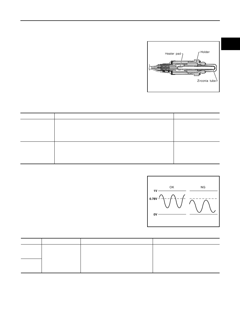
This sensor is made of ceramic zirconia. The zirconia generates volt-
age from approximately 1V in richer conditions to 0V in leaner condi-
tions.
Under normal conditions the heated oxygen sensor 2 is not used for
engine control operation.
CONSULT-III Reference Value in Data Monitor Mode
INFOID:0000000001326672
Specification data are reference values.
On Board Diagnosis Logic
INFOID:0000000001326673
The heated oxygen sensor 2 has a much longer switching time
between rich and lean than the A/F sensor 1. The oxygen storage
capacity of the three way catalyst (manifold) causes the longer
switching time. To judge the malfunctions of heated oxygen sensor
2, ECM monitors whether the maximum voltage of the sensor is suf-
ficiently high during the various driving condition such as fuel-cut.
DTC Confirmation Procedure
INFOID:0000000001326674
NOTE:
If DTC confirmation Procedure has been previously conducted, always turn ignition switch OFF and wait at
least 10 seconds before conducting the next test.
SEF327R
MONITOR ITEM
CONDITION
SPECIFICATION
HO2S2 (B1)
HO2S2 (B2)
• Revving engine from idle to 3,000 rpm quickly after the following conditions
are met.
- Engine: After warming up
- Keeping the engine speed between 3,500 and 4,000 rpm for 1 minute and at
idle for 1 minute under no load
0 - 0.3V
←→
Approx. 0.6 -
1.0V
HO2S2 MNTR (B1)
HO2S2 MNTR (B2)
• Revving engine from idle to 3,000 rpm quickly after the following conditions
are met.
- Engine: After warming up
- Keeping the engine speed between 3,500 and 4,000 rpm for 1 minute and at
idle for 1 minute under no load
LEAN
←→
RICH
PBIB2030E
DTC No.
Trouble diagnosis name
DTC detecting condition
Possible cause
P1147
1147
(Bank 1)
Heated oxygen sensor 2
circuit low voltage
The maximum voltage from the sensor is not
reached to the specified voltage.
• Harness or connectors
(The sensor circuit is open or shorted)
• Heated oxygen sensor 2
• Fuel pressure
• Fuel injector
• Intake air leaks
P1167
1167
(Bank 2)
EC-832
< SERVICE INFORMATION >
[VK45DE]
DTC P0137, P0157 HO2S2
WITH CONSULT-III
TESTING CONDITION:
For better results, perform “DTC WORK SUPPORT” at a temperature of 0 to 30
°
C (32 to 86
°
F).
1.
Turn ignition switch ON and select “COOLAN TEMP/S” in “DATA MONITOR” mode with CONSULT-III.
2.
Start engine and warm it up to the normal operating temperature.
3.
Turn ignition switch OFF and wait at least 10 seconds.
4.
Start engine and keep the engine speed between 3,500 and 4,000 rpm for at least 1 minute under no load.
5.
Let engine idle for 1 minute.
6.
Make sure that “COOLAN TEMP/S” indicates more than 70
°
C (158
°
F).
If not, warm up engine and go to next step when “COOLAN TEMP/S” indication reaches to 70
°
C (158
°
F).
7.
Open engine hood.
8.
Select “HO2S2 (B1) P1147” (for DTC P0137) or “HO2S2 (B2) P1167” (for DTC P0157) of “HO2S2” in
“DTC WORK SUPPORT” mode with CONSULT-III.
9.
Start engine and follow the instruction of CONSULT-III.
NOTE:
It will take at most 10 minutes until “COMPLETED” is displayed.
10. Make sure that “OK” is displayed after touching “SELF-DIAG RESULTS”.
If “NG” is displayed, refer to
.
If “CAN NOT BE DIAGNOSED” is displayed, perform the following.
a.
Turn ignition switch OFF and leave the vehicle in a cool place (soak the vehicle).
b.
Return to step 1.
Overall Function Check
INFOID:0000000001326675
Use this procedure to check the overall function of the heated oxygen sensor 2 circuit. During this check, a 1st
trip DTC might not be confirmed.
WITH GST
1.
Start engine and warm it up to the normal operating temperature.
2.
Turn ignition switch OFF and wait at least 10 seconds.
3.
Start engine and keep the engine speed between 3,500 and 4,000 rpm for at least 1 minute under no load.
4.
Let engine idle for 1 minute.
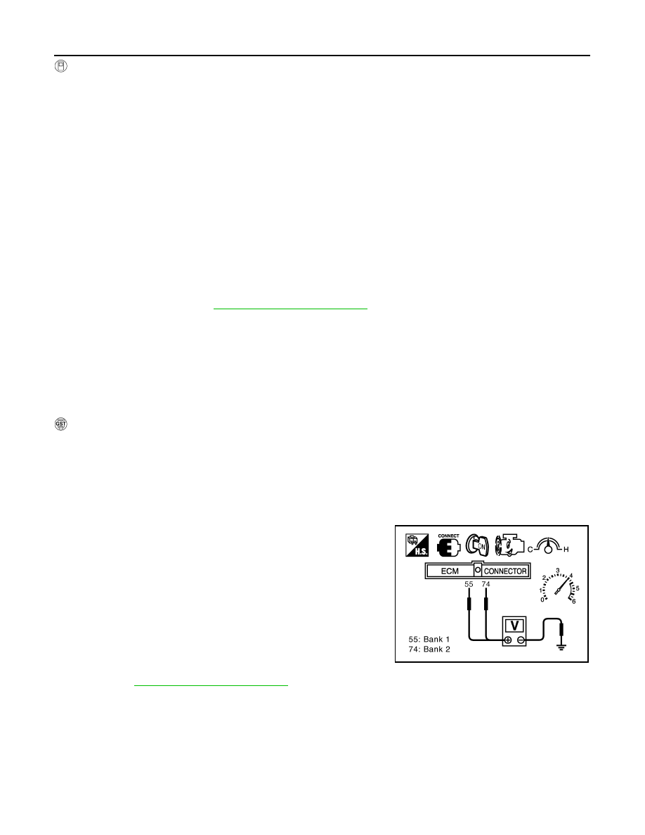
5.
Set voltmeter probes between ECM terminal 55 [HO2S2 (B1) signal] or 74 [HO2S2 (B2) signal] and
ground.
6.
Check the voltage when revving up to 4,000 rpm under no load
at least 10 times.
(Depress and release accelerator pedal as soon as possible.)
The voltage should be above 0.78V at least once during this
procedure.
If the voltage can be confirmed in step 6, step 7 is not nec-
essary.
7.
Keep vehicle at idling for 10 minutes, then check the voltage. Or
check the voltage when coasting from 80 km/h (50 MPH) in D
position.
The voltage should be above 0.78V at least once during this
procedure.
8.
If NG, go to
PBIB2024E
Нет комментариевНе стесняйтесь поделиться с нами вашим ценным мнением.
Текст