Infiniti FX35 / FX45. Manual — part 516
DTC P0133, P0153 A/F SENSOR 1
EC-825
< SERVICE INFORMATION >
[VK45DE]
C
D
E
F
G
H
I
J
K
L
M
A
EC
N
P
O
Do not use ECM ground terminals when measuring input/output voltage. Doing so may result in dam-
age to the ECM's transistor. Use a ground other than ECM terminals, such as the ground.
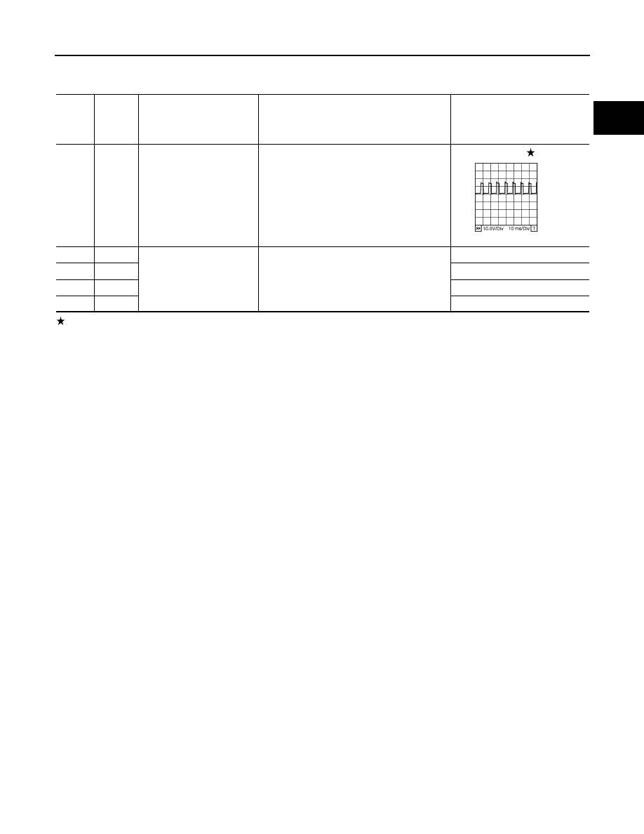
: Average voltage for pulse signal (Actual pulse signal can be confirmed by oscilloscope.)
TER-
MI-
NAL
NO.
WIRE
COLOR
ITEM
CONDITION
DATA (DC Voltage)
2
P
A/F sensor 1 heater
(Bank 1)
[Engine is running]
• Warm-up condition
• Idle speed
Approximately 5V
16
R
A/F sensor 1 (Bank 1)
[Engine is running]
• Warm-up condition
• Idle speed
Approximately 3.1V
35
G
Approximately 2.6V
56
B
Approximately 2.3V
75
OR
Approximately 2.3V
PBIB1584E
EC-826
< SERVICE INFORMATION >
[VK45DE]
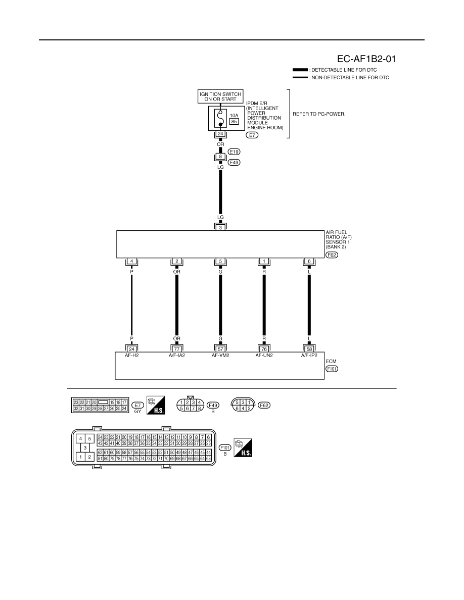
DTC P0133, P0153 A/F SENSOR 1
BANK 2
Specification data are reference values and are measured between each terminal and ground.
Pulse signal is measured by CONSULT-III.
CAUTION:
Do not use ECM ground terminals when measuring input/output voltage. Doing so may result in dam-
age to the ECM's transistor. Use a ground other than ECM terminals, such as the ground.
TBWM1374E
DTC P0133, P0153 A/F SENSOR 1
EC-827
< SERVICE INFORMATION >
[VK45DE]
C
D
E
F
G
H
I
J
K
L
M
A
EC
N
P
O
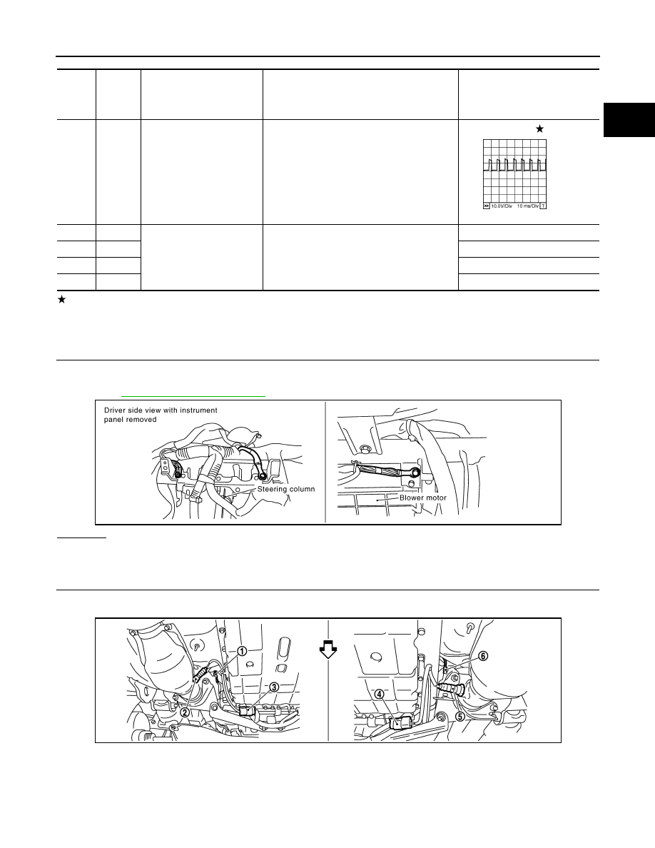
: Average voltage for pulse signal (Actual pulse signal can be confirmed by oscilloscope.)
Diagnosis Procedure
INFOID:0000000001326669
1.
CHECK GROUND CONNECTIONS
1.
Turn ignition switch OFF.
2.
Loosen and retighten three ground screws on the body.
Refer to
OK or NG
OK
>> GO TO 2.
NG
>> Repair or replace ground connections.
2.
RETIGHTEN AIR FUEL RATIO (A/F) SENSOR 1
1.
Loosen and retighten the air fuel ratio (A/F) sensor 1.
TER-
MI-
NAL
NO.
WIRE
COLOR
ITEM
CONDITION
DATA (DC Voltage)
24
P
A/F sensor 1 heater
(Bank 2)
[Engine is running]
• Warm-up condition
• Idle speed
Approximately 5V
57
G
A/F sensor 1 (Bank 2)
[Engine is running]
• Warm-up condition
• Idle speed
Approximately 2.6V
58
L
Approximately 2.3V
76
R
Approximately 3.1V
77
OR
Approximately 2.3V
PBIB1584E
PBIB2195E
1.
A/F sensor 1 (Bank 1)
2.
Heated oxygen sensor 2 (Bank 1)
3.
Heated oxygen sensor 2 (Bank 1)
harness connector
4.
Heated oxygen sensor 2 (Bank 2)
harness connector
5.
Heated oxygen sensor 2 (Bank 2)
6.
A/F sensor 1 (Bank 2)
PBIB3239E
EC-828
< SERVICE INFORMATION >
[VK45DE]
DTC P0133, P0153 A/F SENSOR 1
>> GO TO 3.
3.
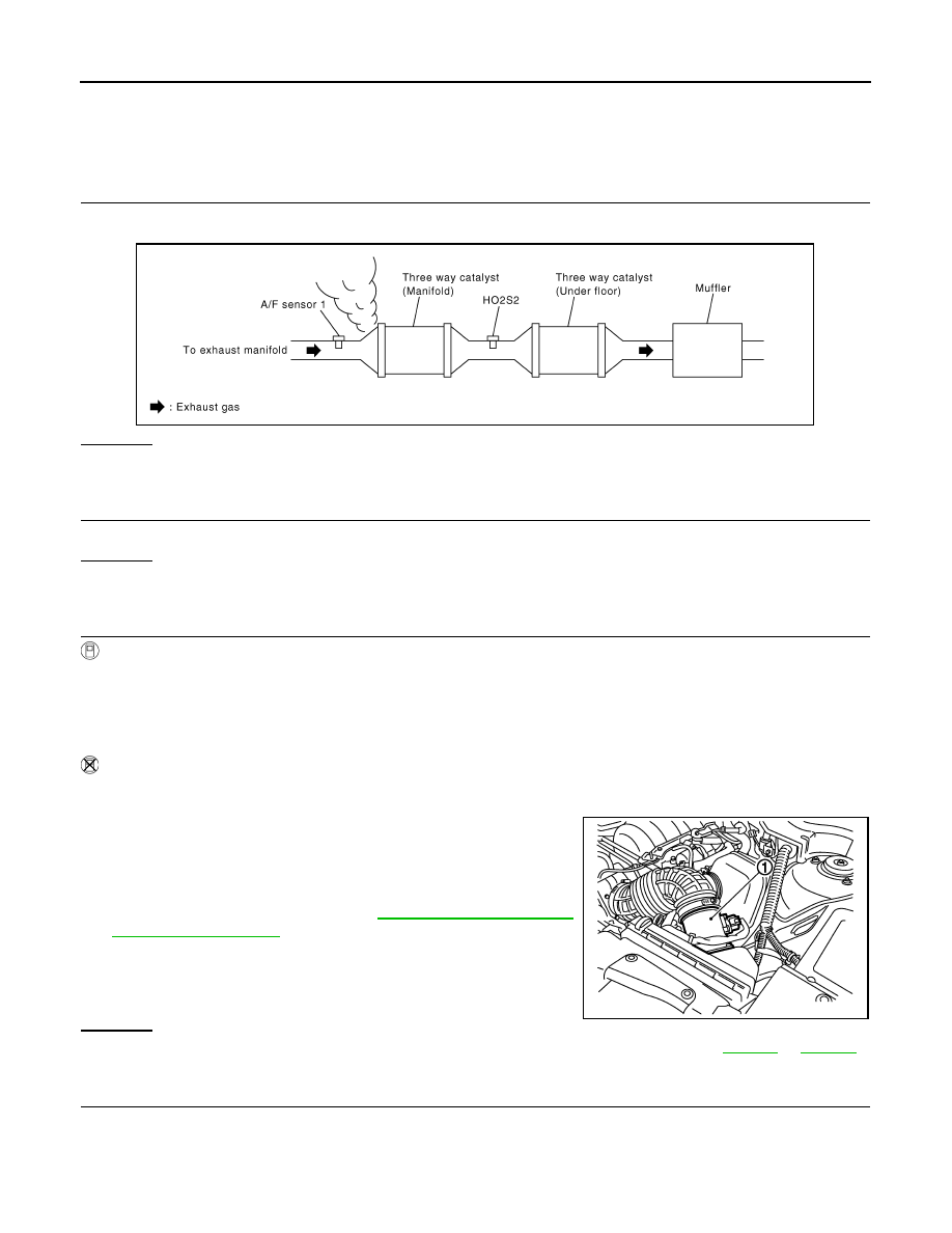
CHECK EXHAUST GAS LEAK
1.
Start engine and run it at idle.
2.
Listen for an exhaust gas leak before three way catalyst (manifold).
OK or NG
OK
>> GO TO 4.
NG
>> Repair or replace.
4.
CHECK FOR INTAKE AIR LEAK
Listen for an intake air leak after the mass air flow sensor.
OK or NG
OK
>> GO TO 5.
NG
>> Repair or replace.
5.
CLEAR THE SELF-LEARNING DATA
With CONSULT-III
1.
Start engine and warm it up to normal operating temperature.
2.
Select “SELF-LEARNING CONT” in “WORK SUPPORT” mode with CONSULT-III.
3.
Clear the self-learning control coefficient by touching “CLEAR” or “START”.
4.
Run engine for at least 10 minutes at idle speed.
Is the 1st trip DTC P0171, P172, P0174 or P0175 detected? Is it difficult to start engine?
Without CONSULT-III
1.
Start engine and warm it up to normal operating temperature.
2.
Turn ignition switch OFF.
3.
Disconnect mass air flow sensor (1) harness connector.
4.
Restart engine and let it idle for at least 5 seconds.
5.
Stop engine and reconnect mass air flow sensor harness con-
nector.
6.
Make sure DTC P0102 is displayed.
7.
Erase the DTC memory. Refer to
8.
Make sure DTC P0000 is displayed.
9.
Run engine for at least 10 minutes at idle speed.
Is the 1st trip DTC P0171, P0172, P0174 or P0175 detected?
Is it difficult to start engine?
Yes or No
Yes
>> Perform trouble diagnosis for DTC P0171, P0174 or P0172, P0175. Refer to
No
>> GO TO 6.
6.
CHECK A/F SENSOR 1 POWER SUPPLY CIRCUIT
1.
Disconnect A/F sensor 1 harness connector.
Tightening torque: 50 N-m (5.1 kg-m, 37 ft-lb)
PBIB1216E
PBIB3230E
Нет комментариевНе стесняйтесь поделиться с нами вашим ценным мнением.
Текст