Infiniti FX35 / FX45. Manual — part 883
RF-14
< SERVICE INFORMATION >
SUNROOF
Terminal and Reference Value for BCM
INFOID:0000000001328038
Terminal and Reference Value for Sunroof Motor Assembly
INFOID:0000000001328039
Ter-
minal
Wire
color
Item
Signal
Input/
Output
Condition
Voltage (V)
(Approx.)
Ignition
switch
OPeration or condition
12 P/B
Front door switch
(passenger side) signal
Input
OFF
OPEN (ON)
0
CLOSE (OFF)
Battery voltage
38
W/L
Ignition switch (ON)
Input
Ignition switch (ON or START) position
Battery voltage
42
L/R
Power source (Fuse)
Input
OFF
—
Battery voltage
49
B
Ground (signal)
—
ON
—
0
52
B
Ground (power)
—
ON
—
0
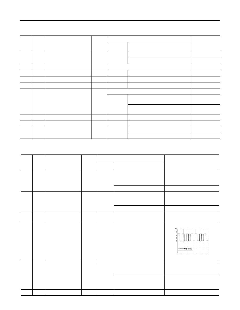
53 Y/B
RAP
signal
Output
Ignition switch ON
Battery voltage
OFF
Within 45 seconds after ignition switch is
turned to OFF position
Battery voltage
When driver side or passenger side door
open in power window timer is operates.
0
54
W
Power window power supply
Output
OFF
—
Battery voltage
55
G
Power source (Fusible link)
Input
OFF
—
Battery voltage
62 W
Front door switch
(driver side) signal
Input
OFF
OPEN (ON)
0
CLOSE (OFF)
Battery voltage
Ter-
minal
Wire
color
Item
Signal
Input/
Output
Condition
Voltage (V)
(Approx.)
Ignition
switch
Operation or condition
1
BR
Sunroof switch (Tilt up/
Slide close) signal
Input
ON
Ignition switch ON and sunroof
switch in TILT UP/SLIDE
CLOSE position
0
Other than above
Battery voltage
5
LG
Sunroof switch
(Tilt down/Slide open)
signal
Input
ON
Ignition switch ON and sunroof
switch in TILT DOWN/SLIDE
OPEN position
0
Other than above
Battery voltage
7
W
Power window power
supply
Input
OFF
—
Battery voltage
8
G
Vehicle speed signal
Input
ON
Speedometer operated
[When vehicle speed is approx.
40 km/h (25 MPH)]
9
SB
RAP signal
Input
Ignition switch ON
Battery voltage
OFF
Within 45 seconds after ignition
switch is turned to OFF position
Battery voltage
When driver side or passenger
side door open in power window
timer is operates.
0
10
B
Ground
—
ON
—
0
ELF1080D
SUNROOF
RF-15
< SERVICE INFORMATION >
C
D
E
F
G
H
J
K
L
M
A
B
RF
N
O
P
Work Flow
INFOID:0000000001328040
1.
Check the symptom and customer's requests.
2.
Understand the outline of system. Refer to
3.
According to the trouble diagnosis chart, repair or replace the cause of the malfunction. Refer to
"Trouble Diagnosis Chart by Symptom"
.
4.
Does sunroof system operate normally? If Yes, GO TO 5. If No, GO TO 3.
5.
INSPECTION END.
CONSULT-III Function (BCM)
INFOID:0000000001328041
ACTIVE TEST
WORK SUPPORT
DATA MONITOR
Trouble Diagnosis Chart by Symptom
INFOID:0000000001328042
BCM diagnostic test item
Check item diagnostic test mode
Content
Refer to page
RETAINED PWR
Work support
Changes setting of each function.
“WORK SUP-
PORT”
Data monitor
Displays the input data of BCM in real time.
“DATA MONI-
TOR”
Active test
Gives a drive signal to a load to check the operation.
“ACTIVE
TEST”
Test Item
Description
RETAINED PWR
This test is able to supply RAP signal (power) from BCM (body control module) to power window
system and power sunroof system (if equipped). Those systems can be operated when turning on
“RETAINED PWR” on CONSULT-III screen even if the ignition switch is turned OFF.
NOTE:
During this test, CONSULT-III can be operated with ignition switch in OFF position. “RETAINED
PWR” should be turned ON or OFF on CONSULT-III screen when ignition switch is ON. Then turn
ignition switch OFF to check retained power operation. CONSULT-III might be stuck if “RETAINED
PWR” is turned to ON or OFF on CONSULT-III screen when ignition switch is OFF.
Work item
Description
RETAINED PWR
Rap signal’s power supply period can be changed by mode setting. Selects rap signal’s power sup-
ply period between three steps
• MODE1 (45 sec.) / MODE2 (OFF) / MODE 3 (2 min.).
Monitor item
Description
IGN ON SW
Indicates [ON / OFF] condition of ignition switch
DOOR SW–DR
Indicates [ON / OFF] condition of front door switch driver side
DOOR SW–AS
Indicates [ON / OFF] condition of front door switch passenger side
Symptom
Diagnostic procedure and repair order
Refer to page
Sunroof does not operate.
1. Check BCM power supply and ground circuit.
2. Check sunroof motor assembly power supply and ground circuit.
3. Check sunroof switch system.
4. Replace sunroof motor assembly.
Motor does not stop at the sunroof fully -open or
fully- closed position.
1. Check initialization procedure.
2. Replace sunroof motor assembly.
RF-16
< SERVICE INFORMATION >
SUNROOF
Check BCM Power Supply and Ground Circuit
INFOID:0000000001328043
1.
CHECK FUSE
• Check 15A fuse [No.1, located in the fuse block (J/B)]
• Check 15A fuse [No.22, located in the fuse block (J/B)]
• Check 50A fusible link (letter M, located in the fuse and fusible link box).
NOTE:
Refer to
RF-10, "Component Parts and Harness Connector Location"
OK or NG
OK
>> GO TO 2.
NG
>> If fuse is blown out, be sure to eliminate cause of malfunction before installing new fuse. Refer to
RF-10, "Component Parts and Harness Connector Location"
2.
CHECK POWER SUPPLY CIRCUIT
1.
Turn ignition switch ON.
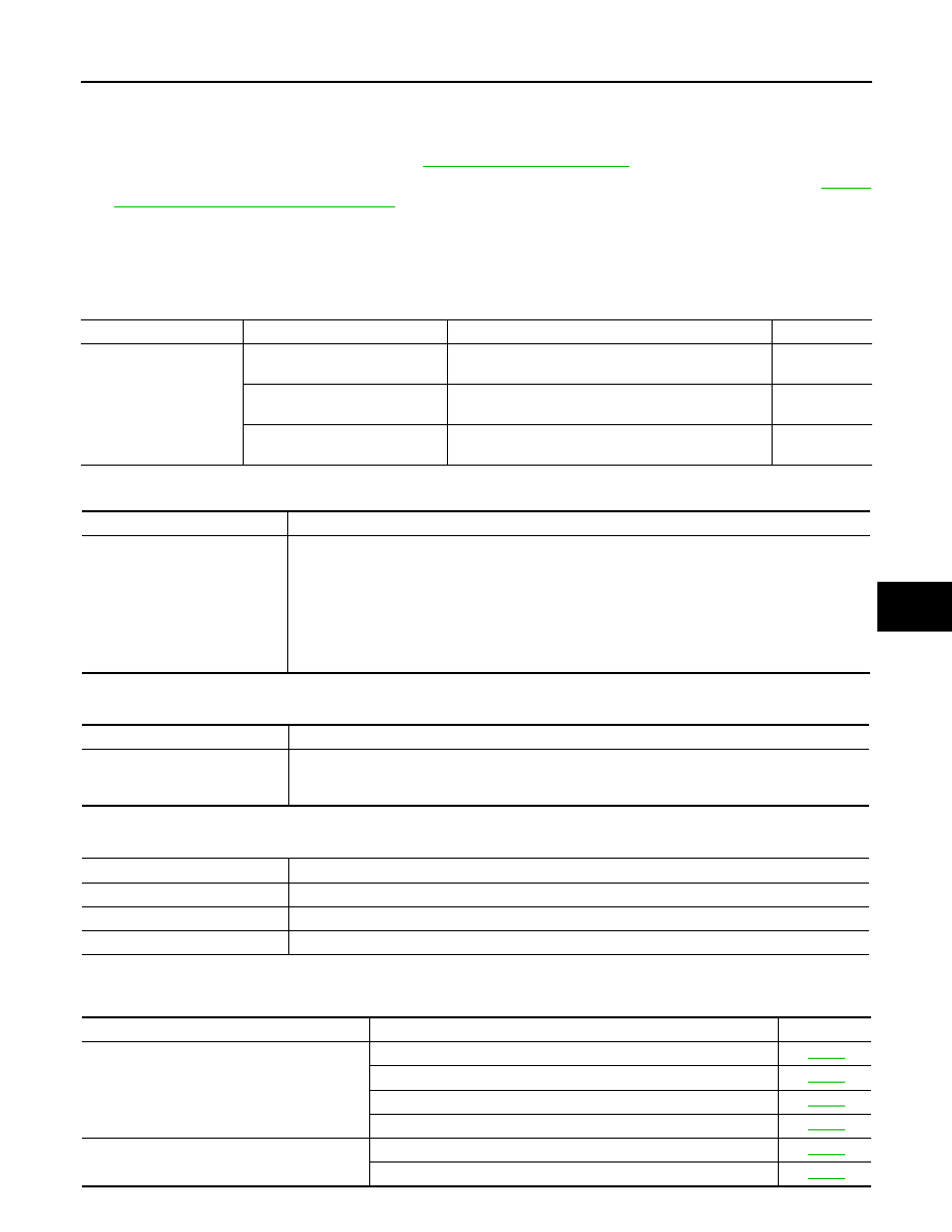
2.
Check voltage between BCM connector M3, M4 terminal 38, 42, 55 and ground.
OK or NG
OK
>> GO TO 3.
NG
>> Check BCM power supply circuit for open or short.
3.
CHECK GROUND CIRCUIT
1.
Turn ignition switch OFF.
2.
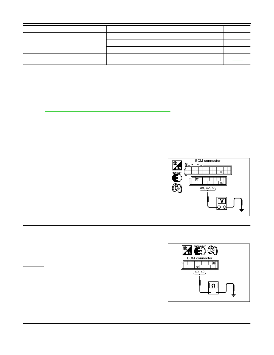
Disconnect BCM connector.
3.
Check continuity between BCM connector M4 terminal 49, 52 and ground.
OK or NG
OK
>> Power supply and ground circuit are OK.
NG
>> Check BCM ground circuit for open or short.
Check Sunroof Motor Assembly Power Supply and Ground Circuit
INFOID:0000000001328044
1.
CHECK POWER SUPPLY CIRCUIT
1.
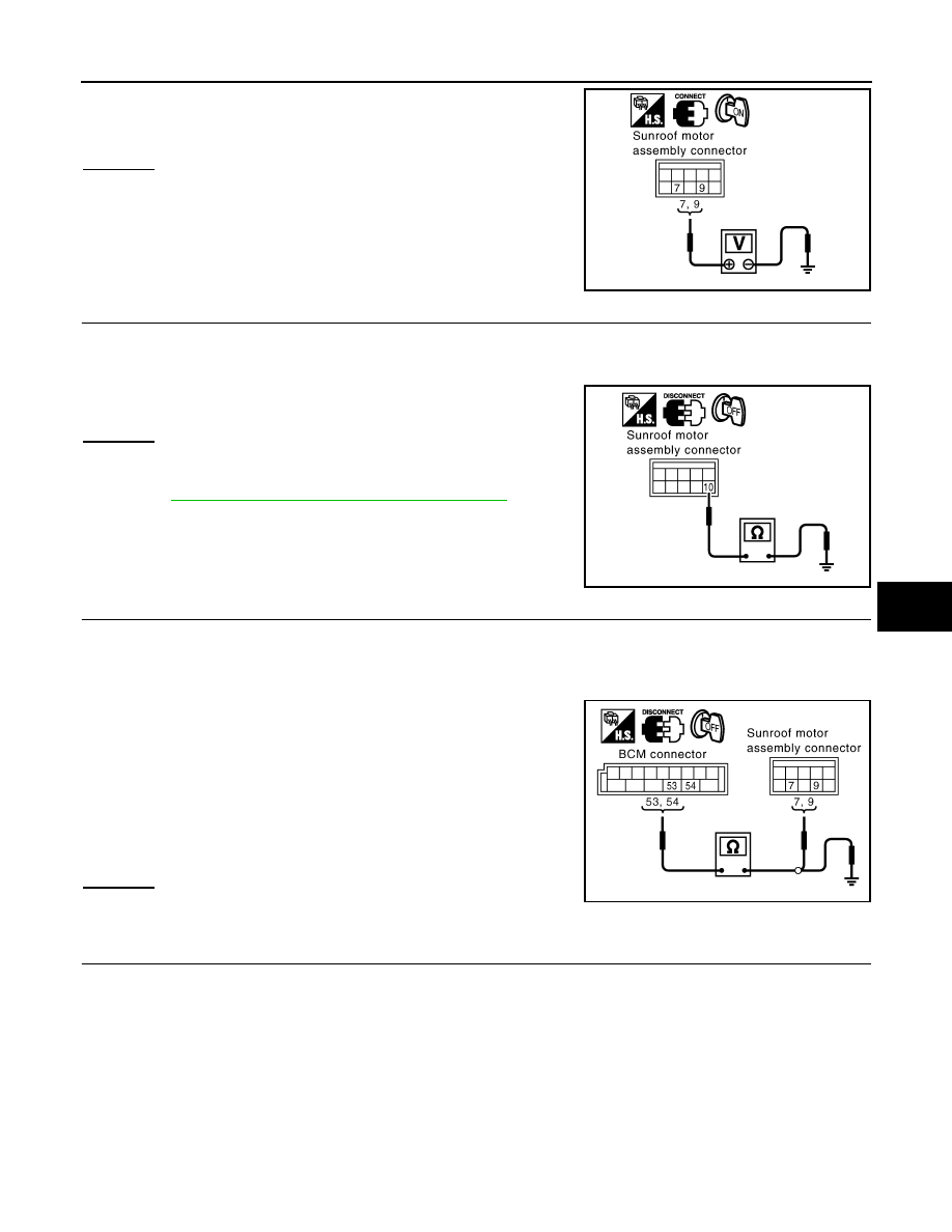
Turn ignition switch ON.
2.
Check voltage between sunroof motor assembly connector R5 terminal 7, 9 and ground.
Retained power operation does not operate
properly.
1. Check the retained power operation mode setting.
2. Check door switch.
3. Replace sunroof motor assembly.
Sunroof does not operate the interruption de-
tection function.
Replace sunroof motor assembly.
Symptom
Diagnostic procedure and repair order
Refer to page
38 (W/L) – Ground
: Battery voltage
42 (L/R) – Ground
: Battery voltage
55 (G) – Ground
: Battery voltage
PIIA6160E
49 (B) – Ground
: Continuity should exist.
52 (B) – Ground
: Continuity should exist.
PIIA6161E
SUNROOF
RF-17
< SERVICE INFORMATION >
C
D
E
F
G
H
J
K
L
M
A
B
RF
N
O
P
OK or NG
OK
>> GO TO 2.
NG
>> GO TO 3.
2.
CHECK GROUND CIRCUIT
1.
Turn ignition switch OFF.
2.
Disconnect sunroof motor assembly connector.
3.
Check continuity between sunroof motor assembly connector R5 terminal 10 and ground.
OK or NG
OK
>> Sunroof motor assembly power supply and ground cir-
cuit are OK. Further inspection is necessary. Refer to
RF-15, "Trouble Diagnosis Chart by Symptom"
NG
>> Repair or replace harness.
3.
CHECK SONROOF MOTOR CIRCUIT
1.
Turn ignition switch OFF.
2.
Disconnect BCM and sunroof motor assembly connector.
3.
Check continuity between BCM connector M4 terminal 53, 54 and sunroof motor assembly connector R5
terminal 7, 9.
4.
Check continuity between BCM connector M4 terminal 53, 54
and ground.
OK or NG
OK
>> GO TO 4.
NG
>> Repair or replace harness.
4.
CHECK BCM OUTPUT SIGNAL
1.
Connect BCM connector.
2.
Turn ignition switch ON.
7 (W) – Ground
: Battery voltage
9 (SB) – Ground
: Battery voltage
PIIA6151E
10 (B) – Ground
: Continuity should exist.
PIIA6152E
53 (Y/B) – 9 (SB)
: Continuity should exist.
54 (W) – 7 (W)
: Continuity should exist.
53 (Y/B) – Ground
: Continuity should not exist.
54 (W) – Ground
: Continuity should not exist.
PIIA6153E
Нет комментариевНе стесняйтесь поделиться с нами вашим ценным мнением.
Текст