Infiniti FX35 / FX45. Manual — part 884
RF-18
< SERVICE INFORMATION >
SUNROOF
3.
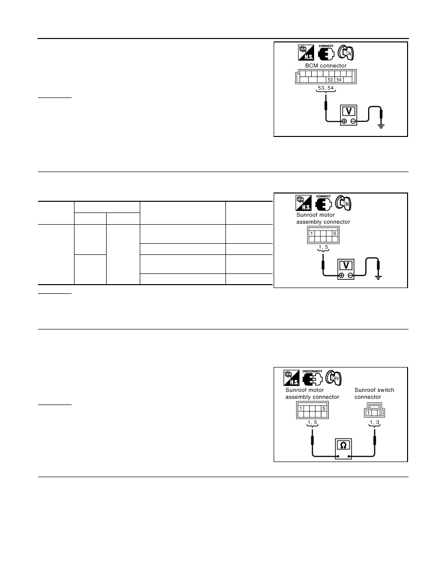
Check voltage between BCM connector M4 terminal 53, 54 and
ground.
OK or NG
OK
>> Check condition of harness and connector.
NG
>> Replace BCM.
Check Sunroof Switch System
INFOID:0000000001328045
1.
CHECK SUNROOF SWITCH INPUT SIGNAL
1.
Turn ignition switch ON.
2.
Check voltage between sunroof motor assembly connector and ground.
OK or NG
OK
>> Replace sunroof motor assembly.
NG
>> GO TO 2.
2.
CHECK SUNROOF SWITCH CIRCUIT
1.
Turn ignition switch OFF.
2.
Disconnect sunroof motor assembly and sunroof switch connector.
3.
Check continuity between sunroof motor assembly connector R5 terminal 1, 5 and sunroof switch connec-
tor R56 terminal 1, 3.
OK or NG
OK
>> GO TO 3.
NG
>> Repair or replace harness between sunroof motor
assembly and sunroof switch.
3.
CHECK SUNROOF SWITCH GROUND CIRCUIT
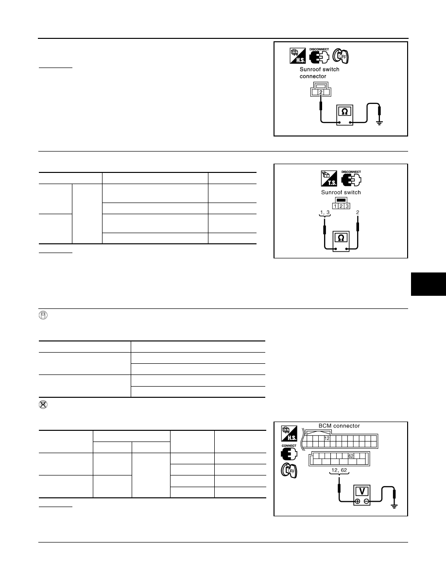
Check continuity between sunroof switch connector R56 terminal 2 and ground.
53 (Y/B) – Ground
: Battery voltage
54 (W) – Ground
: Battery voltage
PIIA6154E
Connector
Terminals (Wire color)
Condition
Voltage (V)
(Approx.)
(+)
(–)
R5
1 (BR)
Ground
Sunroof switch is operated
TILT UP or SLIDE CLOSE
0
Other than above
Battery voltage
5 (LG)
Sunroof switch is operated
TILT DOWN or SLIDE OPEN
0
Other than above
Battery voltage
PIIA6155E
1 (BR) – 3 (BR)
: Continuity should exist.
5 (LG) – 1 (LG)
: Continuity should exist.
PIIA6156E
SUNROOF
RF-19
< SERVICE INFORMATION >
C
D
E
F
G
H
J
K
L
M
A
B
RF
N
O
P
OK or NG
OK
>> GO TO 4.
NG
>> Repair or replace harness.
4.
CHECK SUNROOF SWITCH
Check continuity between sunroof switch terminal 1, 3 and 2.
OK or NG
OK
>> Replace sunroof motor assembly.
NG
>> Replace sunroof switch.
Check Door Switch
INFOID:0000000001328046
1.
CHECK DOOR SWITCH INPUT SIGNAL
With CONSULT-III
Check (“DOOR SW-DR” and “DOOR SW-AS”) in “DATA MONITOR” mode with CONSULT-III.
Without CONSULT-III
Check voltage between BCM connector M3, B14 terminals 12, 62 and ground.
OK or NG
OK
>> Door switch is OK.
NG
>> GO TO 2.
2.
CHECK DOOR SWITCH CIRCUIT
1.
Turn ignition switch OFF.
2 (B) – Ground
: Continuity should exist.
PIIA3627E
Terminals
Condition
Continuity
1
2
Sunroof switch is operated
TILT DOWN or SLIDE OPEN
Yes
Other than above
No
3
Sunroof switch is operated
TILT UP or SLIDE CLOSE
Yes
Other than above
No
PIIA6157E
Monitor item
Condition
DOOR SW-DR
OPEN
: ON
CLOSE
: OFF
DOOR SW-AS
OPEN
: ON
CLOSE
: OFF
Item
Terminals (Wire color)
Condition
Voltage (V)
(Approx.)
(+)
(–)
Passenger side
door switch
12 (P/B)
Ground
OPEN
0
CLOSE
Battery voltage
Driver side door
switch
62 (W)
OPEN
0
CLOSE
Battery voltage
PIIA6158E
RF-20
< SERVICE INFORMATION >
SUNROOF
2.
Disconnect door switch and BCM connector.
3.
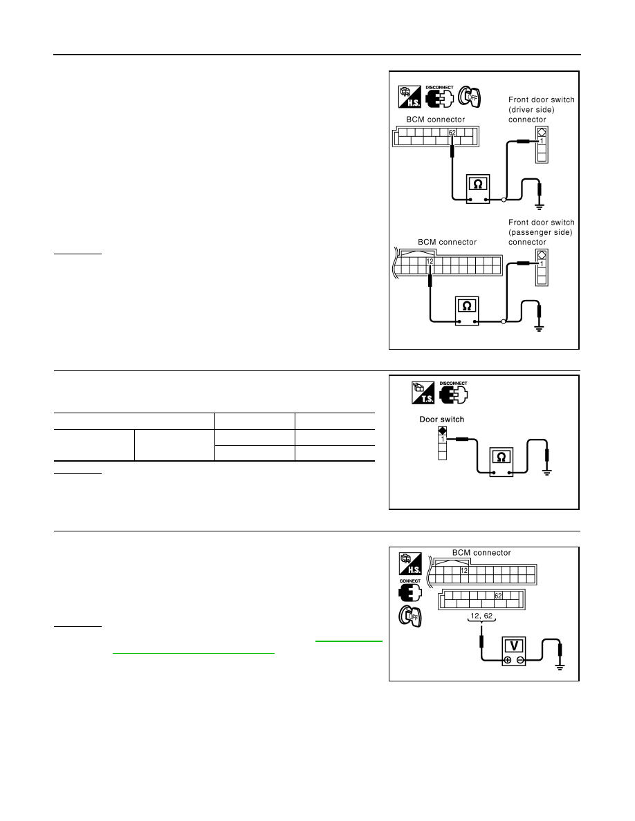
Check continuity between BCM connector M3, B14 terminal 12,
62 and door switch connector B26, B36 terminal 1.
4.
Check continuity between BCM connector M3, B14 terminals
12, 62 and ground.
OK or NG
OK
>> GO TO 3.
NG
>> Repair or replace harness.
3.
CHECK DOOR SWITCH
Check continuity between door switches terminal 1 and ground part
of door switch.
OK or NG
OK
>> GO TO 4.
NG
>> Replace malfunction door switch.
4.
CHECK BCM OUTPUT SIGNAL
1.
Connect BCM connector.
2.
Check voltage between BCM connector M3, B14 terminal 12, 62
and ground.
OK or NG
OK
>> Further inspection is necessary. Refer to
ble Diagnosis Chart by Symptom"
.
NG
>> Replace BCM.
Driver side door
62 (W) – 1 (W)
: Continuity should exist.
Passenger side door
12 (P/B) – 1 (SB)
: Continuity should exist.
12 (P/B) – Ground
: Continuity should not exist.
62 (W) – Ground
: Continuity should not exist.
PIIA6159E
Terminal
Door switch
Continuity
1
Ground part of
door switch
Pushed (close)
No
Released (open)
Yes
PIIA3351E
12 (P/B) – Ground
: Battery voltage
62 (W) – Ground
: Battery voltage
PIIA6158E
SUNROOF
RF-21
< SERVICE INFORMATION >
C
D
E
F
G
H
J
K
L
M
A
B
RF
N
O
P
Wind Deflector Inspection
INFOID:0000000001328047
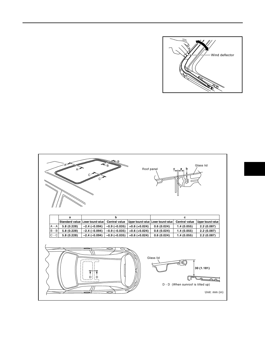
1.
Make sure the wind deflector is properly raised by manual. If a
malfunction is detected, remove and visually check it. If it is
damaged, replace it with a new one. If no damage is found, rein-
stall it properly.
Link and Wire Assembly
INFOID:0000000001328048
NOTE:
Before replacing a suspect part, carefully ensure it is the source of noise being experienced.
1.
Check link to determine if coated film has peeled off to such an extent that substrate is visible. Check also
to determine if link is the source of noise. If it is, replace it.
2.
Visually check to determine if a sufficient amount of grease has been applied to wire or rail groove. If not,
add grease as required.
3.
Check wire for any damage or deterioration. If any damage is found, replace wire.
Fitting Adjustment
INFOID:0000000001328049
LID WEATHERSTRIP OVERLAP ADJUSTMENT AND SURFACE MISMATCH ADJUSTMENT
1.
Tilt up glass lid.
PIIA5061E
PIIA6188E
Нет комментариевНе стесняйтесь поделиться с нами вашим ценным мнением.
Текст