Infiniti FX35 / FX45. Manual — part 255
BRC-6
< SERVICE INFORMATION >
[VDC/TCS/ABS]
PRECAUTIONS
• If the following components are replaced with non-genuine components or converted, VDC OFF indicator
lamp and SLIP indicator lamp may turn on or the VDC system may not operate properly. Components
related to suspension (shock absorber, strut, spring, bushing, etc.), Tires, wheels (exclude specified size),
components related to brake (pad, rotor, caliper, etc.), components related to engine (muffler, ECM, etc.),
components related to body reinforcement (roll bar, tower bar, etc.).
• Driving in the condition of breakage or excessive wear of suspension, tires or components related to the
brakes may cause VDC OFF indicator lamp and SLIP indicator lamp turn on, and the VDC system may not
operate properly.
• When the TCS or VDC is activated by sudden acceleration or sudden turn, some noise may occur. The
noise is a result of the normal operation of the TCS and VDC.
• When driving on roads which have extreme slopes (such as mountainous roads) or high banks (such as
sharp carves on a freeway), the VDC may not operate normally, or VDC OFF indicator lamp and SLIP indi-
cator lamp may turn on. However, this is not a malfunction, if normal operation can be resumed after restart-
ing engine.
• Sudden turns (such as spin turns, acceleration turns), drifting, etc. When VDC function is OFF (VDC OFF
SW ON) may cause the G sensor system indicate a malfunction. However, this is not a malfunction, if nor-
mal operation can be resumed after restarting engine.
• Change 4 tires at a time. Be sure to use specified-size tires that have the same brand name and pattern.
Wheel sensor errors can be detected be self-diagnosis when tires have wide abrasion variations or the size
is different from the genuine tires.
PREPARATION
BRC-7
< SERVICE INFORMATION >
[VDC/TCS/ABS]
C
D
E
G
H
I
J
K
L
M
A
B
BRC
N
O
P
PREPARATION
Special Service Tool
INFOID:0000000001327656
The actual shapes of Kent-Moore tools may differ from those of special service tools illustrated here.
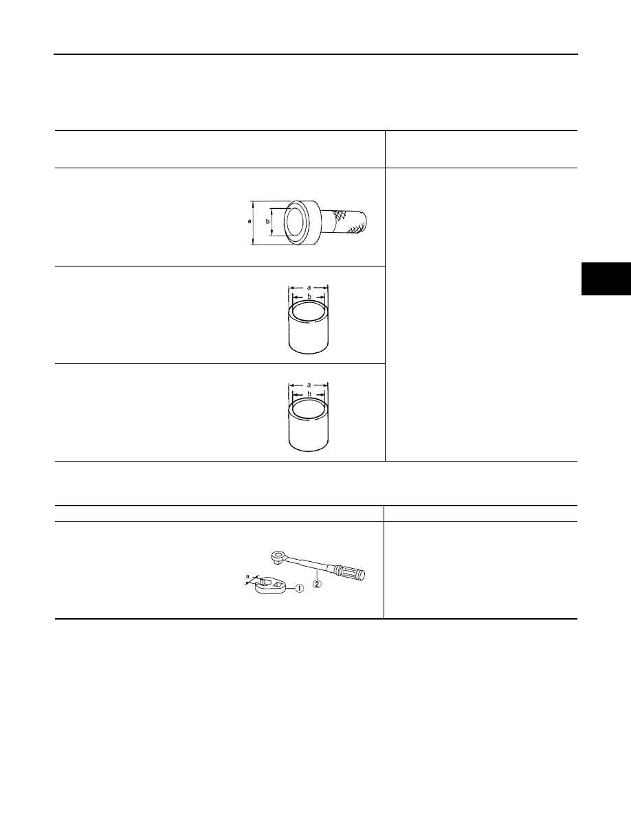
Commercial Service Tool
INFOID:0000000001327657
Tool number
(Kent-Moore No.)
Tool name
Description
ST30720000
(J-25405)
Drift
a: 77 mm (3.03 in) dia.
b: 55.5 mm (2.185 in) dia.
Installing rear sensor rotor
ST27863000
(
—
)
Drift
a: 74.5 mm (2.933 in) dia.
b: 62.5 mm (2.461 in) dia.
KV40104710
(
—
)
Drift
a: 76.3 mm (3.004 in) dia.
b: 67.9 mm (2.673 in) dia.
ZZA0701D
ZZA0832D
ZZA0832D
Tool name
Description
1: Flare nut crowfoot
a: 10 mm (0.39 in)/ 12 mm (0.47 in)
2: Torque wrench
Installing brake tube
S-NT360

BRC-8
< SERVICE INFORMATION >
[VDC/TCS/ABS]
ON-VEHICLE SERVICE
ON-VEHICLE SERVICE
Adjustment of Steering Angle Sensor Neutral Position
INFOID:0000000001327658
In case of doing work that applies to the list below, make sure to adjust neutral position of steering angle sen-
sor before running vehicle.
CAUTION:
To adjust neutral position of steering angle sensor, make sure to use CONSULT-III.
(Adjustment can not be done without CONSULT-III.)
1.
Stop vehicle with front wheels in straight-ahead position.
2.
Touch “WORK SUPPORT” and “ST ANGLE SENSOR ADJUSTMENT” on CONSULT-III screen in this
order.
3.
Touch “START”.
CAUTION:
Do not touch steering wheel while adjusting steering angle sensor.
4.
After approximately 10 seconds, touch “END”. (After approximately 60 seconds, it ends automatically.)
5.
Turn ignition switch OFF, then turn it ON again.
CAUTION:
Be sure to perform above operation.
6.
Run vehicle with front wheels in straight-ahead position, then stop.
7.
Select “DATA MONITOR”, “SELECTION FROM MENU”, and “STR ANGLE SIG” on CONSULT-III screen.
Then make sure “STR ANGLE SIG” is within 0
±
3.5 deg. If value is more than specification, repeat steps
1 to 6.
8.
Erase memory of ABS actuator and electric unit (control unit) and ECM.
9.
Turn ignition switch OFF.
Calibration of Decel G Sensor (AWD Models)
INFOID:0000000001327659
NOTE:
After removing/installing or replacing yaw rate/side/decel G sensor, ABS actuator and electric unit (control
unit), suspension components, or after adjusting wheel alignment, make sure to calibration of decel G sensor
before running vehicle.
CAUTION:
To calibrate decel G sensor, make sure to use CONSULT-III. (Adjustment can not be done without CON-
SULT-III.)
1.
Stop vehicle with front wheels in straight-ahead position.
CAUTION:
• The work should be done at a horizontal place when vehicle is in the unloaded vehicle condition.
• Keep all tires inflated to correct pressures. Adjust the tire pressure to the specified pressure
value.
2.
Touch “WORK SUPPORT” and “DECEL G-SEN CALIBRATION” on CONSULT-III screen in this order.
3.
Touch “START”.
CAUTION:
Set vehicle as shown in the display.
4.
After approximately 10 seconds, touch “END”. (After approximately 60 seconds, it ends automatically.)
Situation
Adjustment of Steering Angle Sensor Neutral Position
Removing/Installing ABS actuator and electric unit (control unit)
—
Replacing ABS actuator and electric unit (control unit)
×
Removing/Installing steering angle sensor
×
Removing/Installing steering components
×
Removing/Installing suspension components
×
Change 4 tires to new ones
—
Tire rotation
—
Adjusting wheel alignment
×
ON-VEHICLE SERVICE
BRC-9
< SERVICE INFORMATION >
[VDC/TCS/ABS]
C
D
E
G
H
I
J
K
L
M
A
B
BRC
N
O
P
5.
Turn ignition switch OFF, then turn it ON again.
CAUTION:
Be sure to perform above operation.
6.
Run vehicle with front wheels in straight-ahead position, then stop.
7.
Select “DATA MONITOR”, “SELECTION FROM MENU”, and “DECEL G-SEN” on CONSULT-III screen.
Then make sure “DECEL G-SEN” is within 0
±
0.08 G. If value is more than specification, repeat steps 1 to
6.
8.
Erase memory of ABS actuator and electric unit (control unit) and ECM.
9.
Turn ignition switch OFF.
Нет комментариевНе стесняйтесь поделиться с нами вашим ценным мнением.
Текст