Infiniti FX35 / FX45. Manual — part 254
BRC-2
DTC C1156 ST ANG SEN COM CIR . . . . . .
DTC C1160 DECEL G SEN SET . . . . . . ...
DTC C1164 CV 1 . . . . . . . . . . . . ....
DTC C1165 CV 2 . . . . . . . . . . . . ....
DTC C1166 SV 1 . . . . . . . . . . . . ....
DTC C1167 SV 2 . . . . . . . . . . . . ....
DTC C1170 VARIANT CODING . . . . . . . .
DTC U1000 CAN COMM CIRCUIT . . . . . ....
Component Inspection . . . . . . . . . . ....
TROUBLE DIAGNOSIS FOR SYMPTOMS . ...
Excessive ABS Function Operation Frequency . ..
Unexpected Pedal Reaction . . . . . . . . ...
The Braking Distance Is Long . . . . . . . ....
The ABS Function Does Not Operate . . . . ....
Pedal Vibration or ABS Operation Sound Occurs ...
Vehicle Jerks During VDC/TCS/ABS Control . . .
WHEEL SENSORS . . . . . . . . . . .
Removal and Installation . . . . . . . . . . .
SENSOR ROTOR . . . . . . . . . . . ..
Removal and Installation . . . . . . . . . . .
ACTUATOR AND ELECTRIC UNIT (ASSEM-
BLY) . . . . . . . . . . . . . . . . ...
Removal and Installation . . . . . . . . . . .
G SENSOR . . . . . . . . . . . . . .
Removal and Installation . . . . . . . . . . .
STEERING ANGLE SENSOR . . . . . . ...
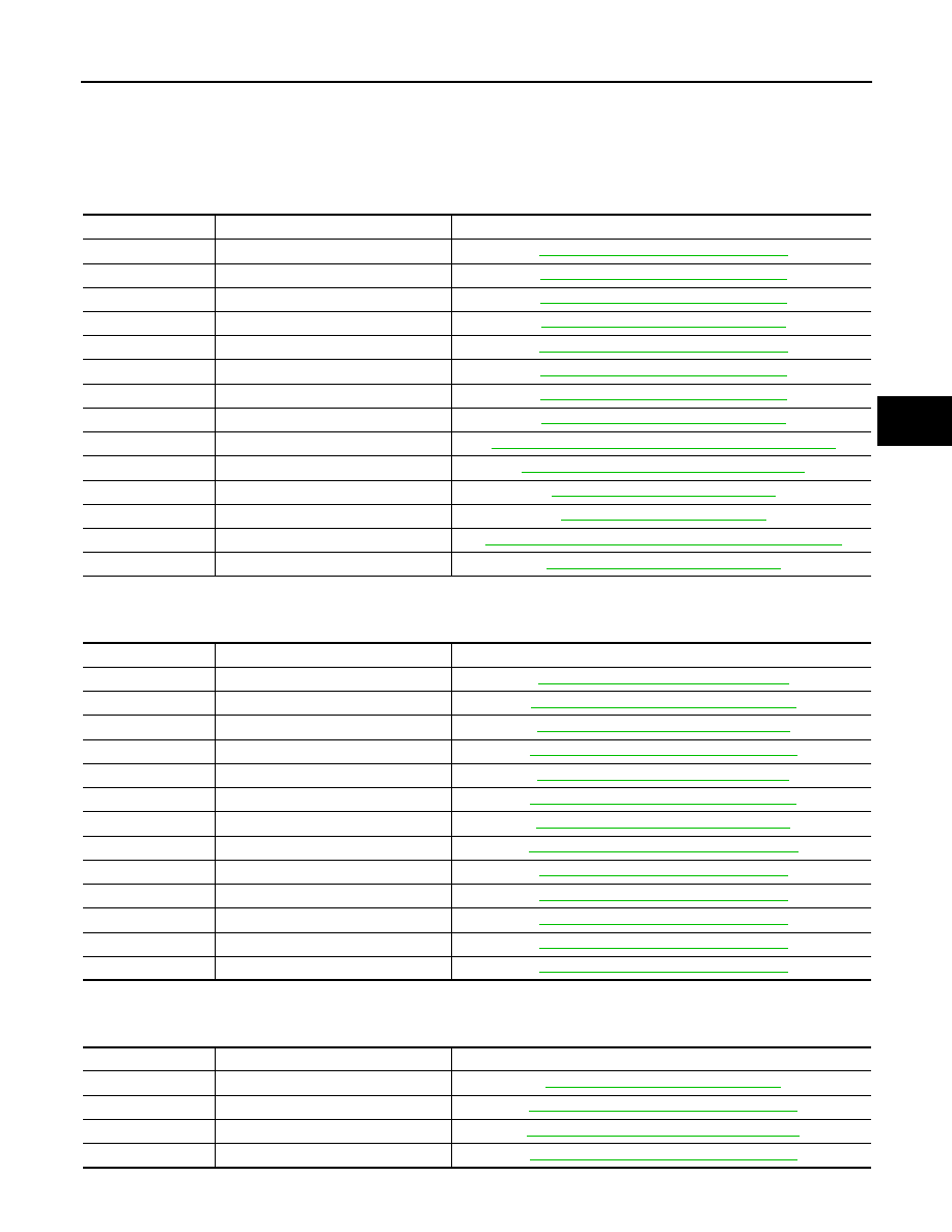
DTC INDEX
BRC-3
< SERVICE INFORMATION >
[VDC/TCS/ABS]
C
D
E
G
H
I
J
K
L
M
A
B
BRC
N
O
P
SERVICE INFORMATION
DTC INDEX
C1101-C1116
INFOID:0000000001559825
C1120-C1136
INFOID:0000000001559826
C1140-C1170
INFOID:0000000001559827
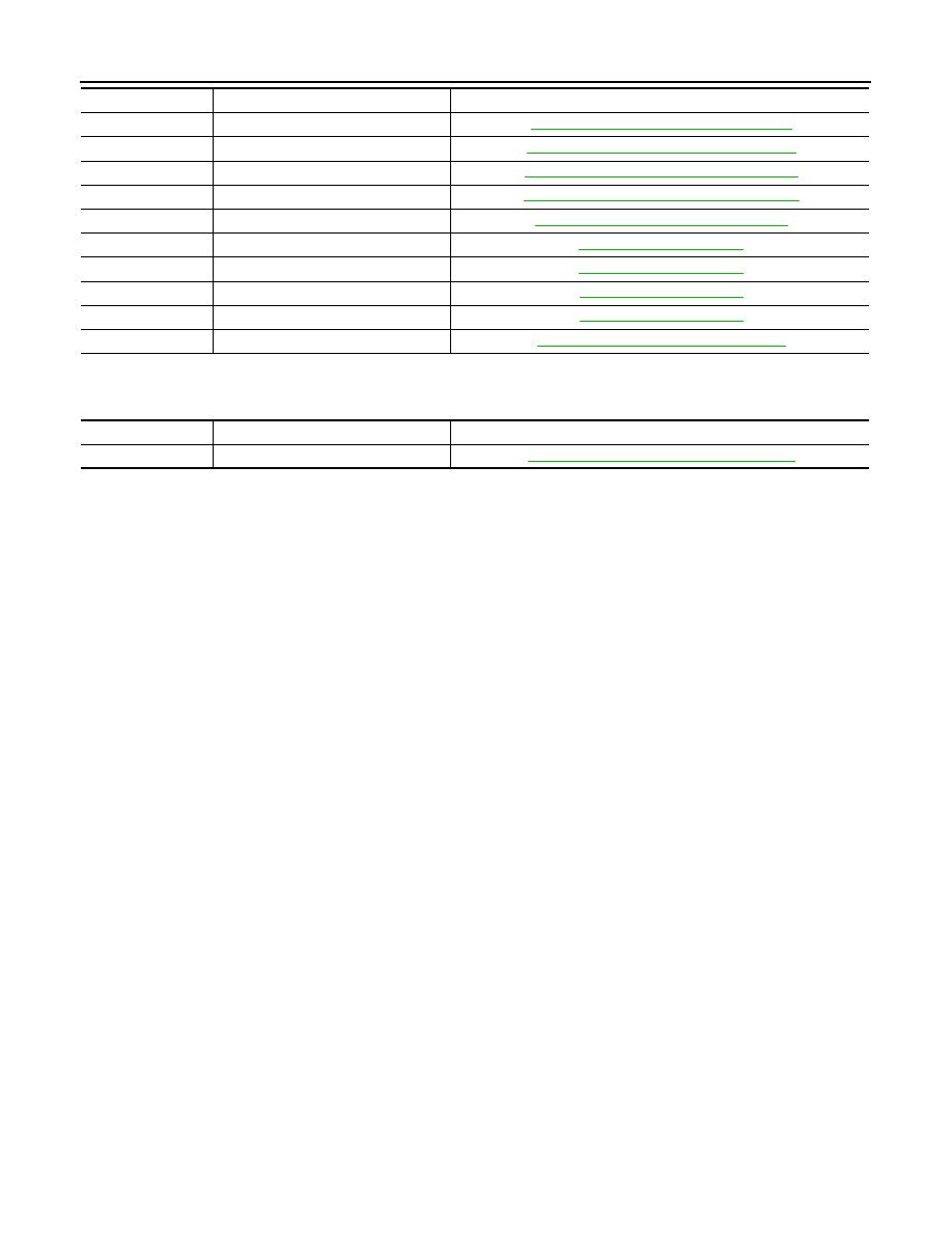
DTC
Items (CONSULT screen items)
Reference
C1101
RR RH SENSOR-1
BRC-34, "DTC C1101 RR RH SENSOR-1"
C1102
RR LH SENSOR-1
BRC-35, "DTC C1102 RR LH SENSOR-1"
C1103
FR RH SENSOR-1
BRC-35, "DTC C1103 FR RH SENSOR-1"
C1104
FR LH SENSOR-1
BRC-35, "DTC C1104 FR LH SENSOR-1"
C1105
RR RH SENSOR-2
BRC-36, "DTC C1105 RR RH SENSOR-2"
C1106
RR LH SENSOR-2
BRC-36, "DTC C1106 RR LH SENSOR-2"
C1107
FR RH SENSOR-2
BRC-36, "DTC C1107 FR RH SENSOR-2"
C1108
FR LH SENSOR-2
BRC-36, "DTC C1108 FR LH SENSOR-2"
C1109
BATTERY VOLTAGE [ABNORMAL]
BRC-36, "DTC C1109 BATTERY VOLTAGE [ABNORMAL]"
C1110
CONTROLLER FAILURE
BRC-37, "DTC C1110 CONTROLLER FAILURE"
C1111
PUMP MOTOR
BRC-37, "DTC C1111 PUMP MOTOR"
C1113
G-SENSOR
C1115
ABS SENSOR [ABNORMAL SIGNAL]
BRC-39, "DTC C1115 ABS SENSOR [ABNORMAL SIGNAL]"
C1116
STOP LAMP SW
BRC-39, "DTC C1116 STOP LAMP SW"
DTC
Items (CONSULT screen items)
Reference
C1120
FR LH IN ABS SOL
BRC-40, "DTC C1120 FR LH IN ABS SOL"
C1121
FR LH OUT ABS SOL
BRC-41, "DTC C1121 FR LH OUT ABS SOL"
C1122
FR RH IN ABS SOL
BRC-41, "DTC C1122 FR RH IN ABS SOL"
C1123
FR RH OUT ABS SOL
BRC-42, "DTC C1123 FR RH OUT ABS SOL"
C1124
RR LH IN ABS SOL
BRC-42, "DTC C1124 RR LH IN ABS SOL"
C1125
RR LH OUT ABS SOL
BRC-42, "DTC C1125 RR LH OUT ABS SOL"
C1126
RR RH IN ABS SOL
BRC-42, "DTC C1126 RR RH IN ABS SOL"
C1127
RR RH OUT ABS SOL
BRC-42, "DTC C1127 RR RH OUT ABS SOL"
C1130
ENGINE SIGNAL 1
BRC-42, "DTC C1130 ENGINE SIGNAL 1"
C1131
ENGINE SIGNAL 2
BRC-42, "DTC C1131 ENGINE SIGNAL 2"
C1132
ENGINE SIGNAL 3
BRC-42, "DTC C1132 ENGINE SIGNAL 3"
C1133
ENGINE SIGNAL 4
BRC-42, "DTC C1133 ENGINE SIGNAL 4"
C1136
ENGINE SIGNAL 6
BRC-42, "DTC C1136 ENGINE SIGNAL 6"
DTC
Items (CONSULT screen items)
Reference
C1140
ACTUATOR RLY
BRC-43, "DTC C1140 ACTUATOR RLY"
C1142
PRESS SEN CIRCUIT
BRC-43, "DTC C1142 PRESS SEN CIRCUIT"
C1143
ST ANG SEN CIRCUIT
BRC-44, "DTC C1143 ST ANG SEN CIRCUIT"
C1144
ST ANG SEN SIGNAL
BRC-4
< SERVICE INFORMATION >
[VDC/TCS/ABS]
DTC INDEX
U1000
INFOID:0000000001559828
C1145
YAW RATE SENSOR
BRC-46, "DTC C1145 YAW RATE SENSOR"
C1146
SIDE G-SEN CIRCUIT
BRC-46, "DTC C1146 SIDE G-SEN CIRCUIT"
C1155
BR FLUID LEVEL LOW
BRC-46, "DTC C1155 BR FLUID LEVEL LOW"
C1156
ST ANG SEN COM CIR
BRC-47, "DTC C1156 ST ANG SEN COM CIR"
C1160
DECEL G SEN SET
BRC-47, "DTC C1160 DECEL G SEN SET"
C1164
CV1
C1165
CV2
C1166
SV1
C1167
SV2
C1170
VARIANT CODING
BRC-48, "DTC C1170 VARIANT CODING"
DTC
Items (CONSULT screen items)
Reference
DTC
Items (CONSULT screen items)
Reference
U1000
CAN COMM CIRCUIT
PRECAUTIONS
BRC-5
< SERVICE INFORMATION >
[VDC/TCS/ABS]
C
D
E
G
H
I
J
K
L
M
A
B
BRC
N
O
P
PRECAUTIONS
Precaution for Supplemental Restraint System (SRS) "AIR BAG" and "SEAT BELT
PRE-TENSIONER"
INFOID:0000000001612923
The Supplemental Restraint System such as “AIR BAG” and “SEAT BELT PRE-TENSIONER”, used along
with a front seat belt, helps to reduce the risk or severity of injury to the driver and front passenger for certain
types of collision. This system includes seat belt switch inputs and dual stage front air bag modules. The SRS
system uses the seat belt switches to determine the front air bag deployment, and may only deploy one front
air bag, depending on the severity of a collision and whether the front occupants are belted or unbelted.
Information necessary to service the system safely is included in the “SUPPLEMENTAL RESTRAINT SYS-
TEM” and “SEAT BELTS” of this Service Manual.
WARNING:
• To avoid rendering the SRS inoperative, which could increase the risk of personal injury or death in
the event of a collision which would result in air bag inflation, all maintenance must be performed by
an authorized NISSAN/INFINITI dealer.
• Improper maintenance, including incorrect removal and installation of the SRS, can lead to personal
injury caused by unintentional activation of the system. For removal of Spiral Cable and Air Bag
Module, see the “SUPPLEMENTAL RESTRAINT SYSTEM”.
• Do not use electrical test equipment on any circuit related to the SRS unless instructed to in this
Service Manual. SRS wiring harnesses can be identified by yellow and/or orange harnesses or har-
ness connectors.
Precaution for Brake System
INFOID:0000000001327654
• Recommended fluid is brake fluid “DOT 3”. Refer to
• Do not reuse drained brake fluid.
• Be careful not to splash brake fluid on painted areas such as body. If brake fluid is splashed, wipe it off and
flush area with water immediately.
• Do not use mineral oils such as gasoline or kerosene to clean. They will ruin rubber parts and cause
improper operation.
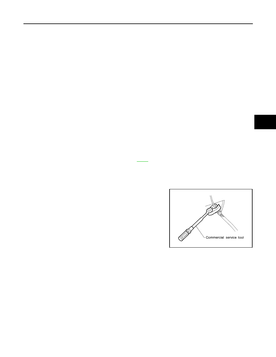
• Using a flare nut crowfoot and torque wrench, securely tighten
brake tube flare nuts.
• Brake system is an important safety part. If a brake fluid leak is
detected, always disassemble the affected part. If a malfunction is
detected, replace part with a new one.
• Before working, turn ignition switch OFF and disconnect electrical
connectors of ABS actuator and electric unit (control unit) or bat-
tery negative terminal.
• When installing brake piping, be sure to check torque.
WARNING:
Clean brake pads and shoes with a waste cloth, then wipe with
a dust collector.
Precaution for Brake Control
INFOID:0000000001327655
• During VDC/TCS/ABS operation, brake pedal lightly vibrates and a mechanical noise may be heard. This is
normal.
• Just after starting vehicle after turning ignition switch ON, brake pedal may vibrate or motor operating noise
may be heard from engine room. This is a normal status of operation check.
• Stopping distance may be longer than that of vehicles without ABS when vehicle drives on rough, gravel, or
snow-covered (fresh, deep snow) roads.
• When an error is indicated by ABS or another warning lamp, collect all necessary information from customer
(what symptoms are present under what conditions) and check for simple causes before starting diagnostic
servicing. Besides electrical system inspection, check booster operation, brake fluid level, and fluid leaks.
• If tire size and type are used in an improper combination, or brake pads are not Genuine NISSAN parts,
stopping distance or steering stability may deteriorate.
• If there is a radio, antenna, or antenna lead-in wire (including wiring) near control module, VDC/TCS/ABS
function may have a malfunction or error.
• If aftermarket parts (car stereo, CD player, etc.) have been installed, check for incidents such as harness
pinches, open circuits, and improper wiring.
SBR686C
Нет комментариевНе стесняйтесь поделиться с нами вашим ценным мнением.
Текст