Infiniti FX35 / FX45. Manual — part 59

AT-164
< SERVICE INFORMATION >
CLOSED THROTTLE POSITION AND WIDE OPEN THROTTLE POSITION CIR-
CUIT
CLOSED THROTTLE POSITION AND WIDE OPEN THROTTLE POSITION
CIRCUIT
CONSULT-III Reference Value in Data Monitor Mode
INFOID:0000000001327353
Diagnosis Procedure
INFOID:0000000001327354
1.
CHECK CAN COMMUNICATION LINE
With CONSULT-III
• Perform the self-diagnosis.
Without CONSULT-III
• Perform the self-diagnosis. Refer to
AT-91, "Diagnosis Procedure without CONSULT-III"
.
Is a malfunction in the CAN communication indicated in the results?
YES
>> Check CAN communication line. Refer to
NO
>> GO TO 2.
2.
CHECK THROTTLE POSITION SIGNAL CIRCUIT
With CONSULT-III
1.
Turn ignition switch ON.
2.
Select “ECU INPUT SIGNALS” in “DATA MONITOR” mode for “TRANSMISSION” with CONSULT-III.
3.
Depress accelerator pedal and read out the value of “CLSD THL POS” and “W/O THL POS”.
OK or NG
OK
>> INSPECTION END
NG
>>
Check the following items. If NG, repair or replace damaged parts.
• Perform the self-diagnosis for “ENGINE” with CONSULT-III. Refer to
EC-695, "CONSULT-III Function (ENGINE)"
• Open circuit or short to ground or short to power in harness or connectors.
• Pin terminals for damage or loose connection with harness connector.
Item name
Condition
Display value
CLSD THL POS
Released accelerator pedal.
ON
Fully depressed accelerator pedal.
OFF
W/O THL POS
Fully depressed accelerator pedal.
ON
Released accelerator pedal.
OFF
Accelerator Pedal Operation
Monitor Item
CLSD THL POS
W/O THL POS
Released
ON
OFF
Fully depressed
OFF
ON
BRAKE SIGNAL CIRCUIT
AT-165
< SERVICE INFORMATION >
D
E
F
G
H
I
J
K
L
M
A
B
AT
N
O
P
BRAKE SIGNAL CIRCUIT
CONSULT-III Reference Value in Data Monitor Mode
INFOID:0000000001327355
Diagnosis Procedure
INFOID:0000000001327356
1.
CHECK CAN COMMUNICATION LINE
With CONSULT-III
• Perform the self-diagnosis.
Without CONSULT-III
• Perform the self-diagnosis. Refer to
AT-91, "Diagnosis Procedure without CONSULT-III"
.
Is a malfunction in the CAN communication indicated in the results?
YES
>> Check CAN communication line. Refer to
NO
>> GO TO 2.
2.
CHECK STOP LAMP SWITCH CIRCUIT
With CONSULT-III
1.
Turn ignition switch ON.
2.
Select “ECU INPUT SIGNALS” in “DATA MONITOR” mode for “TRANSMISSION” with CONSULT-III.
3.
Read out ON/OFF switching action of the “BRAKE SW”.
OK or NG
OK
>> INSPECTION END
NG
>> GO TO 3.
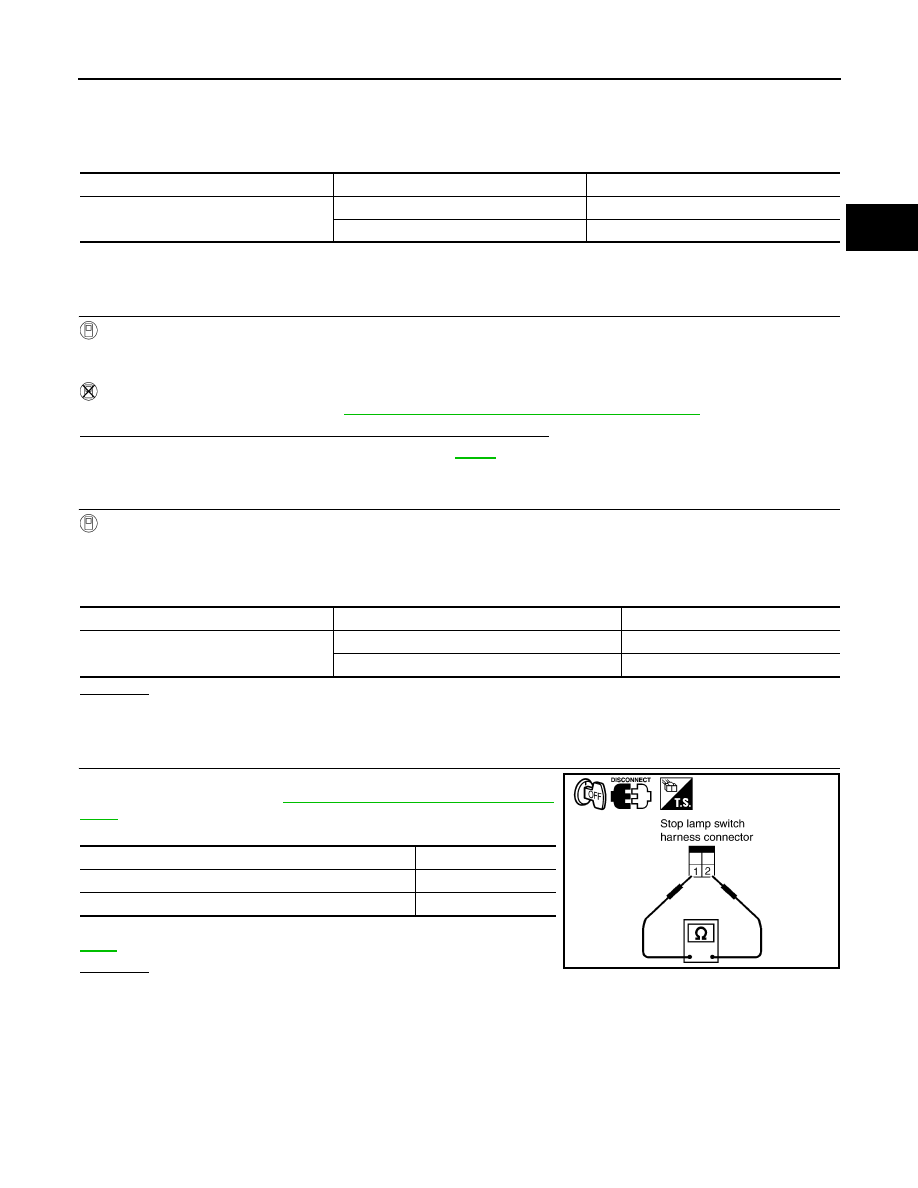
3.
CHECK STOP LAMP SWITCH
Check continuity between stop lamp switch harness connector E210
terminals 1 and 2. Refer to
AT-167, "Wiring Diagram - AT - NON-
Check stop lamp switch after adjusting brake pedal — refer to
OK or NG
OK
>>
Check the following items. If NG, repair or replace damaged parts.
• Harness for short or open between battery and stop lamp switch.
• Harness for short or open between stop lamp switch and unified meter and A/C amp.
NG
>> Repair or replace the stop lamp switch.
Item name
Condition
Display value
BRAKE SW
Depressed brake pedal.
ON
Released brake pedal.
OFF
Item name
Condition
Display value
BRAKE SW
Depressed brake pedal.
ON
Released brake pedal.
OFF
Condition
Continuity
When brake pedal is depressed
Yes
When brake pedal is released
No
SCIA2144E
AT-166
< SERVICE INFORMATION >
A/T INDICATOR CIRCUIT
A/T INDICATOR CIRCUIT
Description
INFOID:0000000001327357
TCM sends the switch signals to unified meter and A/C amp. by CAN communication line. Then manual mode
switch position is indicated on the A/T indicator.
CONSULT-III Reference Value in Data Monitor Mode
INFOID:0000000001327358
Diagnosis Procedure
INFOID:0000000001327359
1.
CHECK INPUT SIGNALS
With CONSULT-III
1.
Start engine.
2.
Select “MAIN SIGNALS” in “DATA MONITOR” mode for “TRANSMISSION” with CONSULT-III and read
out the value of “GEAR”.
3.
Drive vehicle in the manual mode, and confirm that the actual gear position and the meter's indication of
the position mutually coincide when the selector lever is shifted to the “+ (up)” or “- (down)” side (1st
⇔
5th
gear).
OK or NG
OK
>> INSPECTION END
NG
>> Check the following.
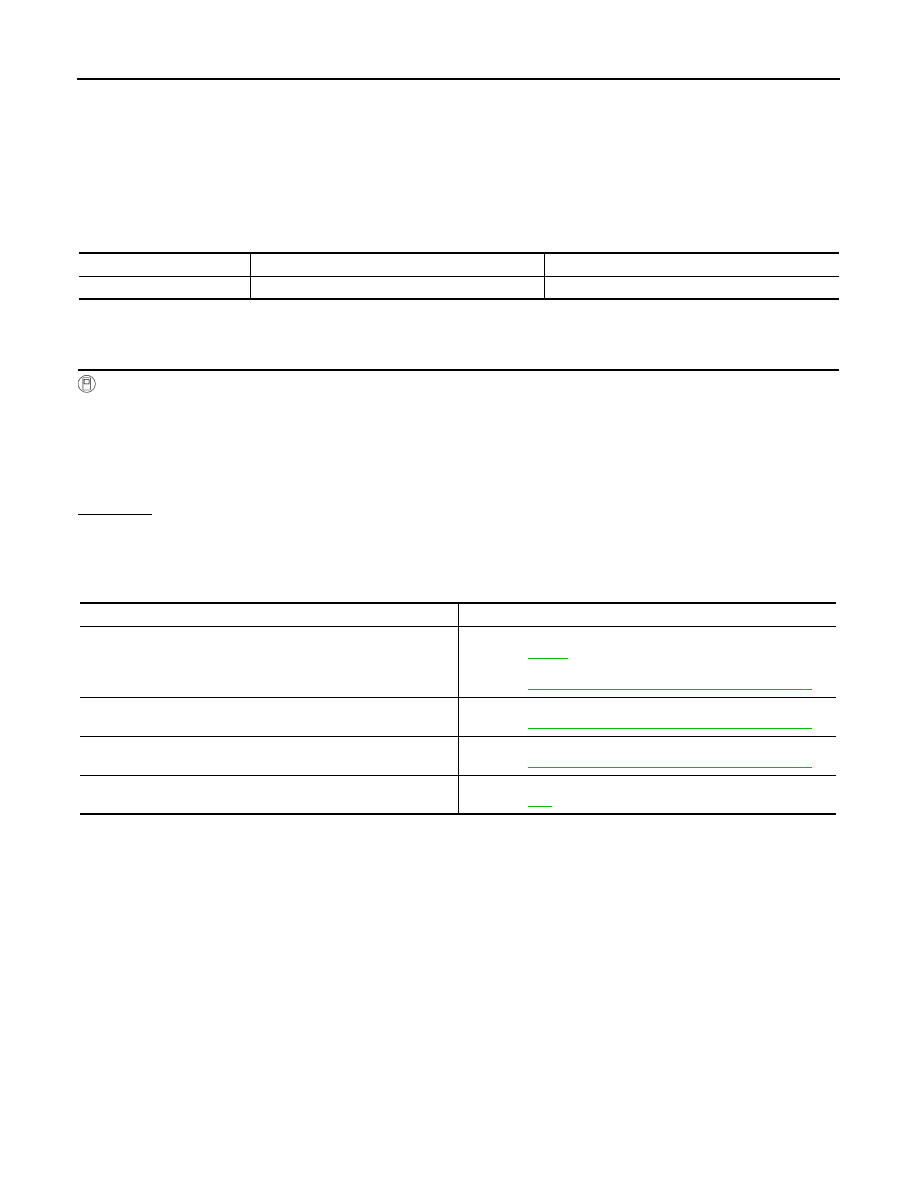
A/T INDICATOR SYMPTOM CHART
Item name
Condition
Display value
GEAR
During driving
1, 2, 3, 4, 5
Items
Presumed Location of Trouble
The actual gear position does not change, or shifting into the man-
ual mode is not possible (no gear shifting in the manual mode pos-
sible).
The A/T indicator is not indicated.
A/T main system (Fail-safe function actuated)
• Refer to
AT-84, "CONSULT-III Function (TRANSMISSION)"
The actual gear position changes, but the A/T indicator is not indi-
cated.
Perform the self-diagnosis function.
• Refer to
AT-84, "CONSULT-III Function (TRANSMISSION)"
The actual gear position and the indication on the A/T indicator do
not coincide.
Perform the self-diagnosis function.
• Refer to
AT-84, "CONSULT-III Function (TRANSMISSION)"
Only a specific position or positions is/are not indicated on the A/
T indicator.
TROUBLE DIAGNOSIS FOR SYMPTOMS
AT-167
< SERVICE INFORMATION >
D
E
F
G
H
I
J
K
L
M
A
B
AT
N
O
P
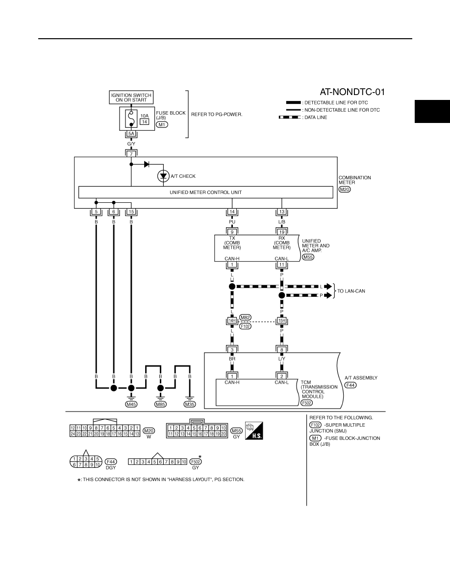
TROUBLE DIAGNOSIS FOR SYMPTOMS
Wiring Diagram - AT - NONDTC
INFOID:0000000001327360
TCWM0500E
Нет комментариевНе стесняйтесь поделиться с нами вашим ценным мнением.
Текст