Infiniti FX35 / FX45. Manual — part 57
AT-156
< SERVICE INFORMATION >
DTC P1815 MANUAL MODE SWITCH
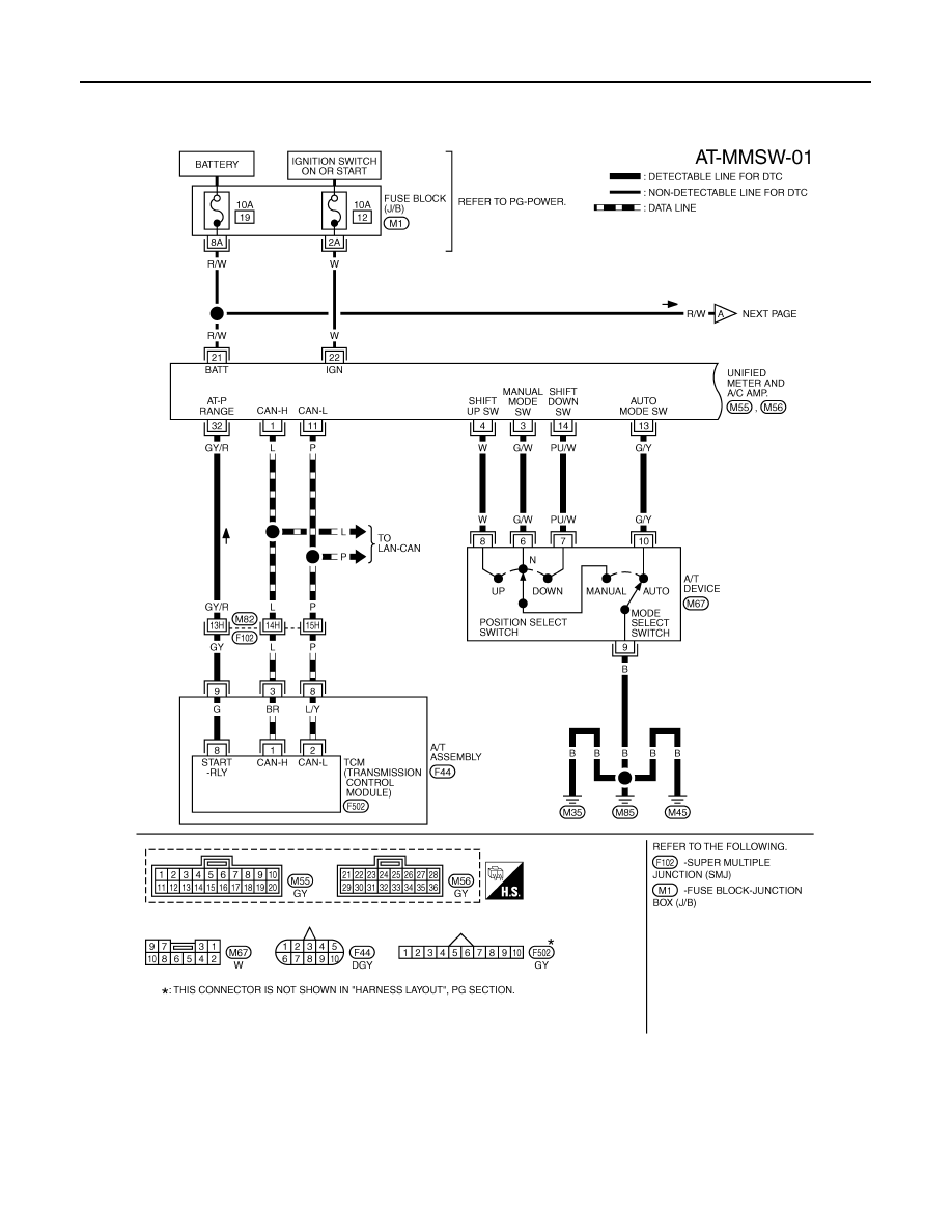
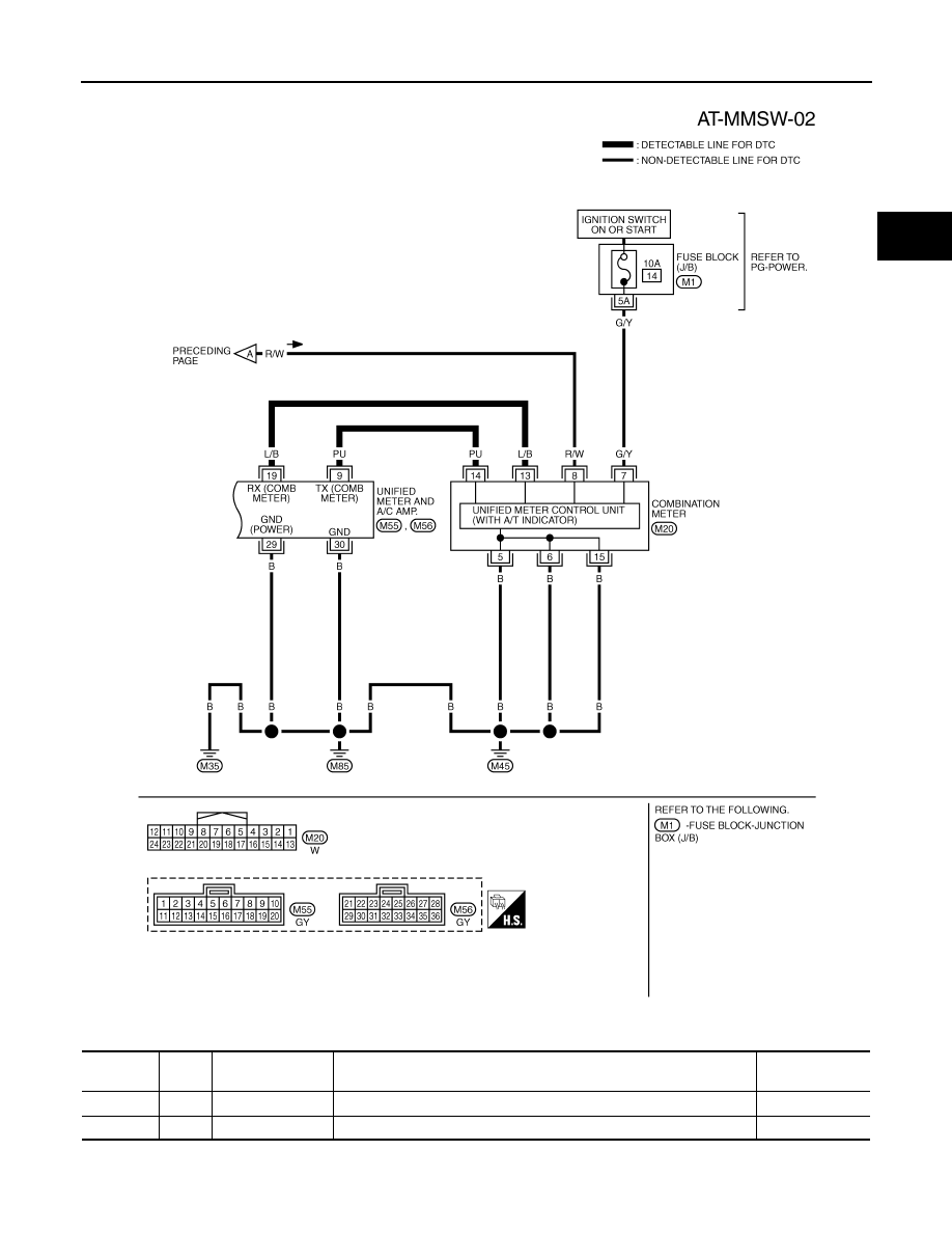
Wiring Diagram - AT - MMSW
INFOID:0000000001327324
TCWM0498E
DTC P1815 MANUAL MODE SWITCH
AT-157
< SERVICE INFORMATION >
D
E
F
G
H
I
J
K
L
M
A
B
AT
N
O
P
TCM terminals and data are reference value. Measured between each terminal and ground.
TCWM0499E
Terminal
Wire
color
Item
Condition
Data (Approx.)
3
L
CAN-H
–
–
8
P
CAN-L
–
–
AT-158
< SERVICE INFORMATION >
DTC P1815 MANUAL MODE SWITCH
Diagnosis Procedure
INFOID:0000000001327325
1.
CHECK CAN COMMUNICATION LINE
Perform the self-diagnosis.
Is a malfunction in the CAN communication indicated in the results?
YES
>> Check CAN communication line. Refer to
NO
>> GO TO 2.
2.
CHECK MANUAL MODE SWITCH CIRCUIT
With CONSULT-III
1.
Turn ignition switch ON.
2.
Select “ECU INPUT SIGNALS” in “DATA MONITOR” mode for “TRANSMISSION” with CONSULT-III.
3.
Read out ON/OFF switching action of “MANU MODE SW”, “NON M-MODE SW”, “UP SW LEVER”,
“DOWN SW LEVER”.
Without CONSULT-III
Drive vehicle in the manual mode, and confirm that the actual gear position and the meter's indication of the
position mutually coincide when the selector lever is shifted to the “+ (up)” or “- (down)” side (1st
⇔
5th gear).
OK or NG
OK
>> GO TO 4.
NG
>> GO TO 3.
3.
DETECT MALFUNCTIONING ITEM
Check the following.
• Manual mode switch. Refer to
AT-159, "Component Inspection"
.
• Pin terminals for damage or loose connection with harness connector.
• Open circuit or short to ground or short to power in harness or connector for A/T device (manual mode
switch).
• Unified meter and A/C amp. Refer to
OK or NG
OK
>> GO TO 4.
NG
>> Repair or replace damaged parts.
4.
CHECK DTC
Perform
AT-155, "DTC Confirmation Procedure"
.
OK or NG
OK
>> INSPECTION END
NG
>> GO TO 5.
9
GY
Starter relay
Selector lever in “N” and “P” positions.
Battery voltage
Selector lever in other positions.
0 V
Terminal
Wire
color
Item
Condition
Data (Approx.)
Item name
Condition
Display Value
MANU MODE SW
Manual shift gate position (neutral)
ON
Other than the above
OFF
NON M-MODE SW
Manual shift gate position
OFF
Other than the above
ON
UP SW LEVER
selector lever: +side
ON
Other than the above
OFF
DOWN SW LEVER
selector lever: -side
ON
Other than the above
OFF
DTC P1815 MANUAL MODE SWITCH
AT-159
< SERVICE INFORMATION >
D
E
F
G
H
I
J
K
L
M
A
B
AT
N
O
P
5.
CHECK TCM POWER SUPPLY AND GROUND CIRCUIT
Check TCM power supply and ground circuit. Refer to
.
OK or NG
OK
>> GO TO 6.
NG
>> Repair or replace damaged parts.
6.
DETECT MALFUNCTIONING ITEM
Check A/T assembly harness connector pin terminals for damage or loose connection with harness connector.
OK or NG
OK
>> Replace the control valve with TCM. Refer to
AT-215, "Control Valve with TCM and A/T Fluid Tem-
.
NG
>> Repair or replace damaged parts.
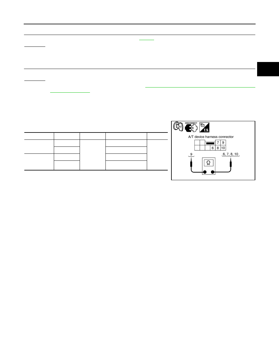
Component Inspection
INFOID:0000000001327326
MANUAL MODE SWITCH
Check continuity between terminals.
Item
Position
Connector Terminal
Continuity
Manual mode
select switch
Auto
M67
9 - 10
Yes
Manual
6 - 9
Manual mode
position select
switch
UP
8 - 9
DOWN
7 - 9
SCIA2112E
Нет комментариевНе стесняйтесь поделиться с нами вашим ценным мнением.
Текст