Infiniti FX35 / FX45. Manual — part 829
LU-28
< SERVICE INFORMATION >
[VK45DE]
OIL COOLER
6.
Remove water pipe, as necessary.
INSPECTION AFTER REMOVAL
Oil Cooler
Check oil cooler for cracks. Check oil cooler for clogging by blowing through engine coolant inlet. If necessary,
replace oil cooler.
Relief Valve
Check relief valve for movement, cracks and breaks by pushing the ball. If replacement is necessary, remove
relief valve by prying it out with suitable tool. Install a new valve in place by tapping it.
INSTALLATION
Note the following, and install in the reverse order of removal.
• Make sure that no foreign objects are adhering to the installation planes of oil cooler or oil pan.
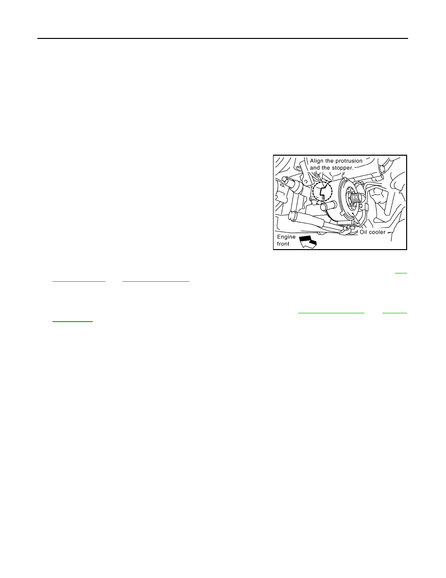
• Tighten connector bolt after aligning stopper on the oil pan side
with protrusion of oil cooler.
INSPECTION AFTER INSTALLATION
1.
Make sure level of engine oil and engine coolant, and adjust engine oil and engine coolant. Refer to
2.
Start engine, and make sure there is no leak of engine oil or engine coolant.
3.
Stop engine and wait for 15 minutes.
4.
Check the engine oil level and the engine coolant level again. Refer to
PBIC1527E
OIL PUMP
LU-29
< SERVICE INFORMATION >
[VK45DE]
C
D
E
F
G
H
I
J
K
L
M
A
LU
N
P
O
OIL PUMP
Component
INFOID:0000000001325834
Removal and Installation
INFOID:0000000001325835
REMOVAL
1.
Remove engine assembly from vehicle. Refer to
2.
Remove front cover. Refer to
3.
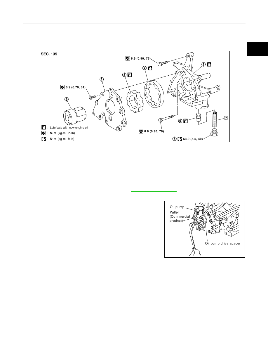
Remove oil pump drive spacer.
• Set bolts in the two bolt holes [M6
×
pitch 1.0 mm (0.04 in)] on
the front surface. Using suitable puller, pull oil pump drive
spacer off from crankshaft.
NOTE:
The dimension between the centers of the two bolt holes is 33
mm (1.30 in).
In the figure, a commercial steering puller is used.
4.
Remove oil pump.
INSTALLATION
1.
Install the oil pump.
2.
Install oil pump drive spacer as follows:
1.
Oil pump body
2.
Oil pump outer rotor
3.
Oil pump inner rotor
4.
Oil pump cover
5.
Oil pump drive spacer
6.
Regulator valve
7.
Regulator valve spring
8.
Regulator valve plug
PBIC1592E
PBIC0054E
LU-30
< SERVICE INFORMATION >
[VK45DE]
OIL PUMP
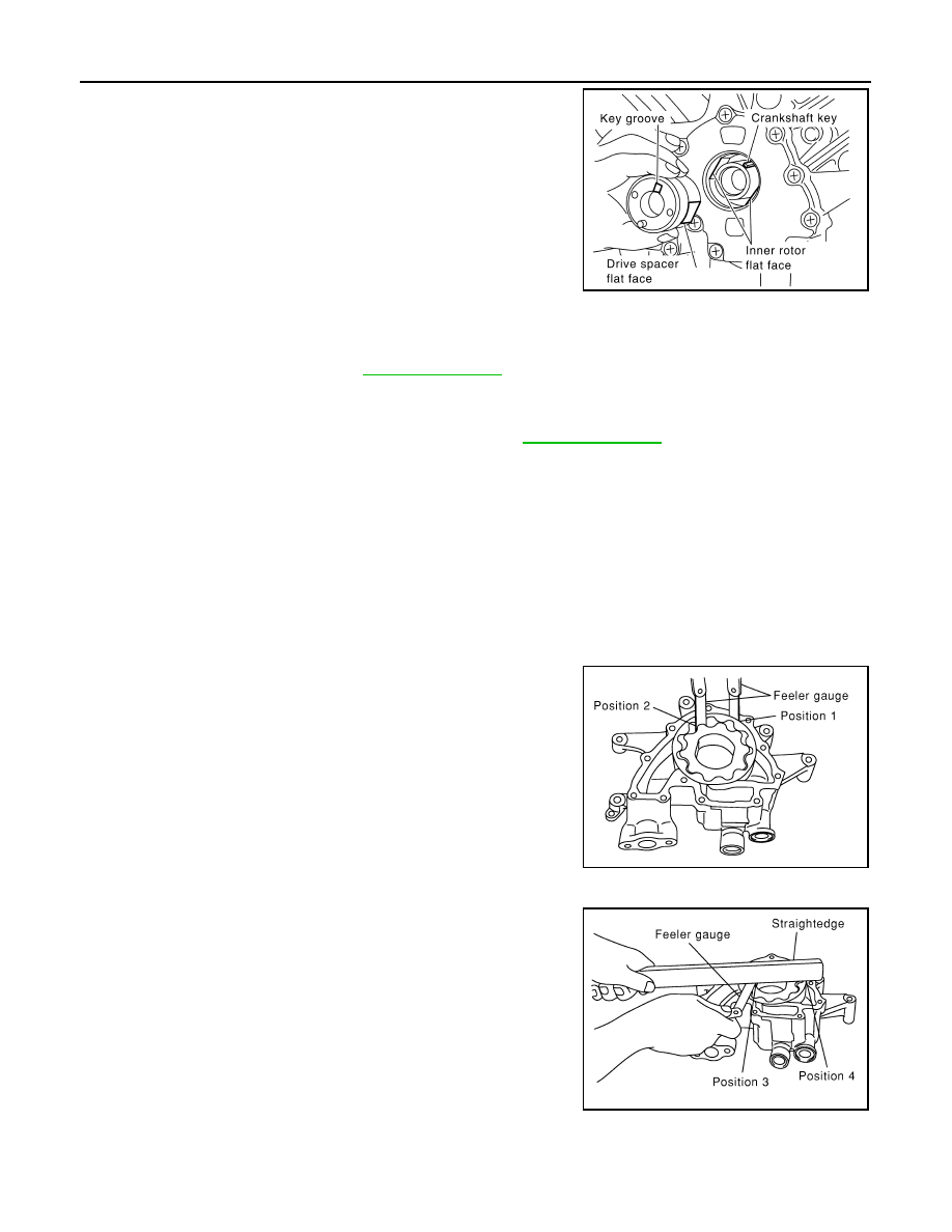
a.
Insert oil pump drive spacer according to the directions of crank-
shaft key and the two flat surfaces of oil pump inner rotor.
• If the positional relationship does not allow the insertion, rotate
oil pump inner rotor with a finger to allow spacer.
b.
After confirming that the position of each part is in correct condi-
tion to allow for spacer, force fit spacer by lightly tapping with
plastic hammer until it contacts and does not go further.
3.
Install in the reverse order of removal after this step.
INSPECTION AFTER INSTALLATION
1.
Check the engine oil level. refer to
2.
Start engine, and check there is no leak of engine oil.
3.
Stop engine and wait for 15 minutes.
4.
Check the engine oil level and adjust engine oil. Refer to
.
Disassembly and Assembly
INFOID:0000000001325836
DISASSEMBLY
1.
Remove oil pump cover.
2.
Remove oil pump inner rotor and oil pump outer rotor from oil pump body.
3.
After removing regulator valve plug, remove regulator valve spring and regulator valve.
INSPECTION AFTER DISASSEMBLY
Oil Pump Clearance
• Measure the clearance with feeler gauge.
- Clearance between oil pump outer rotor and oil pump body (Posi-
tion 1)
- Tip clearance between oil pump inner rotor and oil pump outer
rotor (Position 2)
• Measure the clearance with feeler gauge and straightedge.
- Side clearance between oil pump inner rotor and oil pump body
(Position 3)
- Side clearance between oil pump outer rotor and oil pump body
(Position 4)
• Calculate the clearance between oil pump inner rotor and oil pump body as follows:
OIL PUMP INNER ROTOR OUTER DIAMETER
PBIC0058E
Standard
: 0.114 - 0.200 mm (0.0045 - 0.0079 in)
Standard
: Below 0.180 mm (0.0071 in)
PBIC0139E
Standard
: 0.030 - 0.070 mm (0.0012 - 0.0028 in)
Standard
: 0.030 - 0.090 mm (0.0012 - 0.0035 in)
PBIC0140E
OIL PUMP
LU-31
< SERVICE INFORMATION >
[VK45DE]
C
D
E
F
G
H
I
J
K
L
M
A
LU
N
P
O
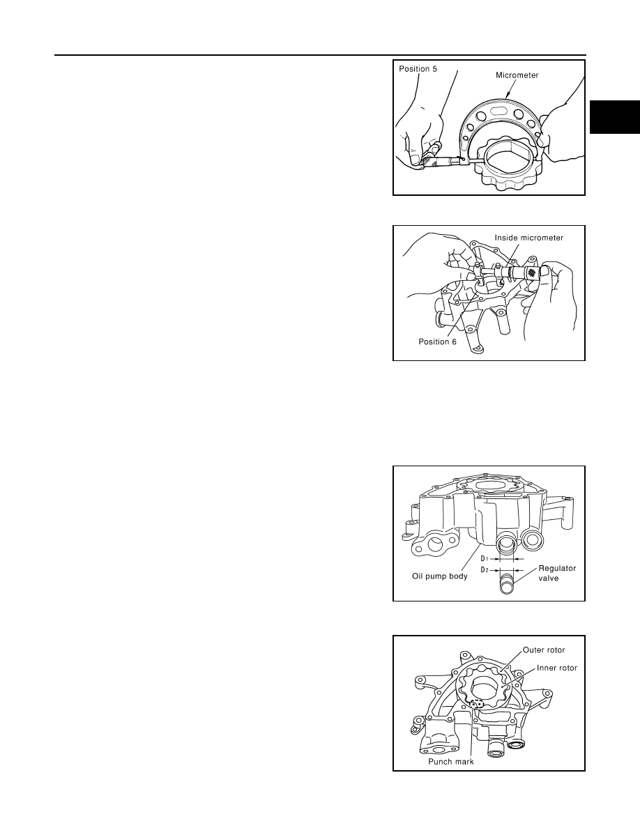
- Measure the outer diameter of protruded portion of oil pump inner
rotor with micrometer. (Position 5)
OIL PUMP BODY INNER DIAMETER
- Measure the inner diameter of oil pump body with inside microme-
ter. (Position 6)
OIL PUMP INNER DIAMETER TO OIL PUMP BODY CLEARANCE
- (Clearance) = (Oil pump body inner diameter) – (Oil pump inner rotor outer diameter)
• If the measured/calculated values are out of the standard, replace oil pump assembly.
Regulator Valve Clearance
(Clearance) = D
1
(Valve hole diameter) – D
2
(Regulator valve outer
diameter of valve)
• If the calculated value is out of the standard, replace oil pump
assembly.
CAUTION:
• Coat regulator valve with engine oil.
• Make sure that it falls smoothly into regulator valve hole by its
own weight.
ASSEMBLY
Note the following, and assemble in the reverse order of disassembly.
• Install oil pump inner rotor and oil pump outer rotor with the
punched marks on the oil pump cover side.
PBIC0141E
PBIC0142E
Standard
: 0.045 - 0.091 mm (0.0018 - 0.0036 in)
Standard
: 0.040 - 0.097 mm (0.0016 - 0.0038 in)
PBIC0143E
PBIC0144E
Нет комментариевНе стесняйтесь поделиться с нами вашим ценным мнением.
Текст