Infiniti FX35 / FX45. Manual — part 868
PS-14
< SERVICE INFORMATION >
STEERING COLUMN
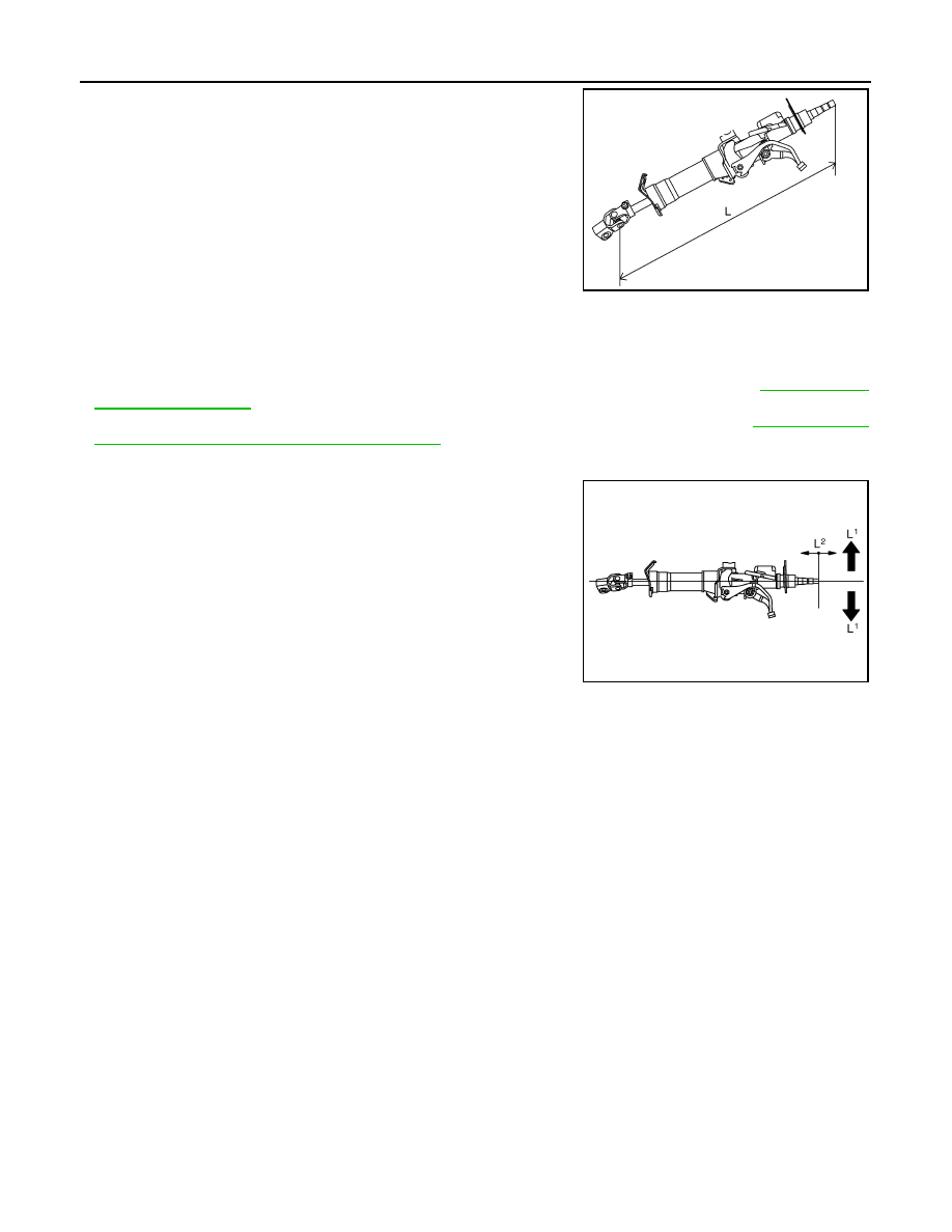
• If vehicle has a collision light shocked, check column length “L” as
shown in the figure. Then if it is out of the specified value, replace
with new one.
• Check the turning torque of steering column with preload gauge
(SST). If it is out of the specified value, repair it or replace with new
one.
INSTALLATION
• Refer to "COMPONENTS" for tightening torque. Install in the reverse order of removal.
NOTE:
Refer to component parts location and do not reuse non-reusable parts.
• After removing/installing or replacing steering components, check wheel alignment. Refer to
.
• After adjusting wheel alignment, adjust neutral position of steering angle sensor. Refer to
ment of Steering Angle Sensor Neutral Position"
INSPECTION AFTER INSTALLATION
• Check tilt and telescopic mechanism operating range “L
1
”, “L
2
” as
shown in the figure.
• Check if steering wheel operation can turn to the end of the left and
right smoothly.
Disassembly and Assembly
INFOID:0000000001327715
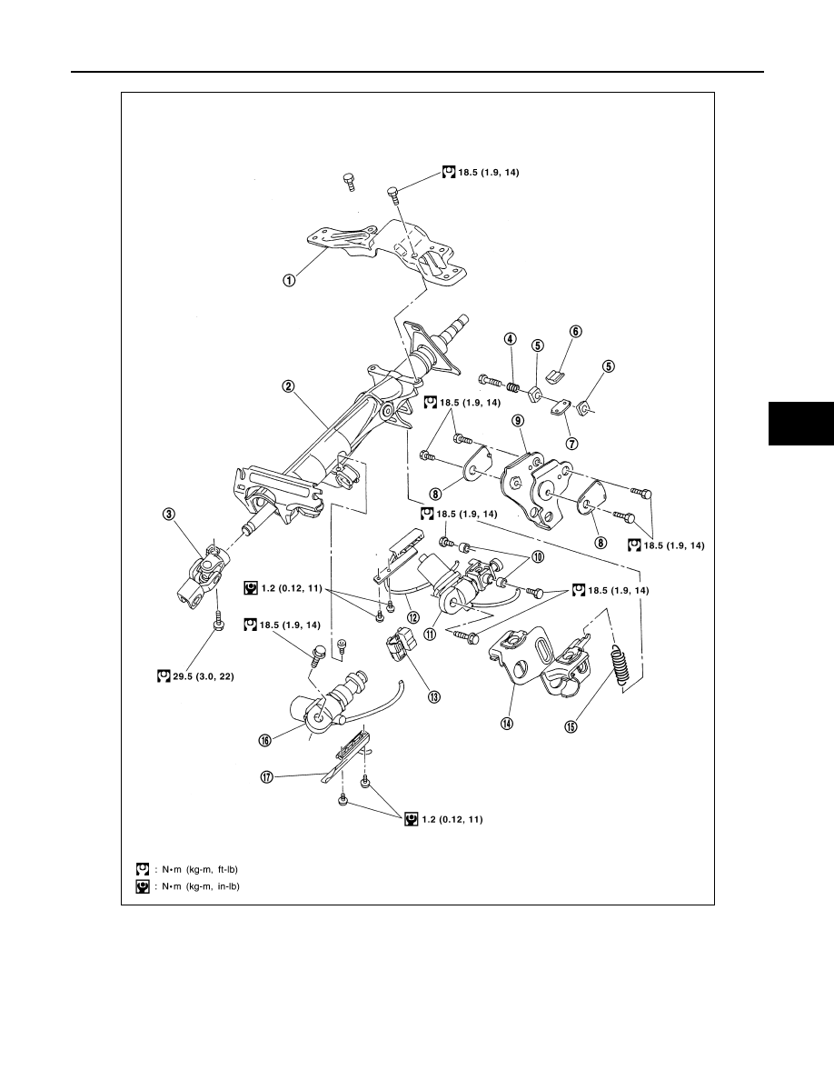
COMPONENTS
Steering column length “L”: 572 mm (22.52 in)
Turning torque
: 0
−
0.2 N·m (0
−
0.021 kg-m, 0
−
1 in-lb)
SGIA0556E
Tilt operating range “L
1
”
: 28 - 32 mm (1.1 - 1.26 in)
Telescopic operating range
“L
2
”
: 18 - 22 mm (0.71 - 0.87 in)
SGIA1431E
STEERING COLUMN
PS-15
< SERVICE INFORMATION >
C
D
E
F
H
I
J
K
L
M
A
B
PS
N
O
P
1.
Meter bracket
2.
Jacket tube assembly
3.
Upper joint
4.
Spring
5.
Lock nut
6.
Lock block
7.
Telescopic lock guide
8.
Bush spacer
9.
Tilt link assembly
10. Cooler
11.
Tilt unit assembly
12. Tilt sensor assembly
13. Connector assembly
14. Clamp
15. Spring
16. Telescopic unit assembly
17. Telescopic sensor assembly
SGIA0592E
PS-16
< SERVICE INFORMATION >
STEERING COLUMN
DISASSEMBLY
Disassemble the parts from jacket tube. The parts to be disassembled are shown in the figure.
ASSEMBLY
Refer to "COMPONENTS" for tightening torque. Install in the reverse order of disassembly.
POWER STEERING GEAR AND LINKAGE
PS-17
< SERVICE INFORMATION >
C
D
E
F
H
I
J
K
L
M
A
B
PS
N
O
P
POWER STEERING GEAR AND LINKAGE
Removal and Installation
INFOID:0000000001327716
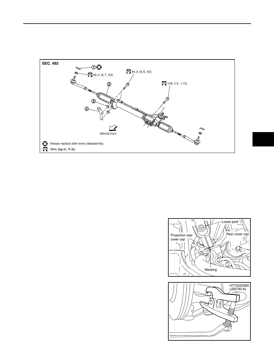
COMPONENTS
CAUTION:
Spiral cable may snap due to steering operation if steering column is separated from steering gear
assembly. Therefore fix steering wheel with a string to avoid turns.
REMOVAL
1.
Set wheels in the straight-ahead position.
2.
Remove tires from vehicle with power tool.
3.
Remove undercover with power tool.
4.
Confirm slit of lower joint fits with the projection on rear cover
cap, furthermore marking position on steering gear assembly
nearly fits with the projection on rear cover cap.
5.
Remove cotter pin at steering outer socket, then loosen mount-
ing nut.
6.
Use a ball joint remover (SST) to remove steering outer socket
from steering knuckle. Be careful not to damage ball joint boot.
CAUTION:
Tighten temporarily mounting nut to prevent damage to
threads and to prevent ball joint remover (SST) from com-
ing off.
1.
Cotter pin
2.
Steering gear assembly
3.
Washer
4.
Clip
SGIA1432E
SGIA0539E
SDIA1434E
Нет комментариевНе стесняйтесь поделиться с нами вашим ценным мнением.
Текст